A glue tank removal equipment for LED lamp dispensing

A technology of LED lights and glue cans, which is applied to spray devices, devices that apply liquid to the surface, coatings, etc., can solve the problems of removing glue, easy to get glue on people's hands, and difficult to glue the inner wall of the can.

Active Publication Date: 2020-11-24
浙江罗丹照明电器有限公司
View PDF3 Cites 1 Cited by
  • Summary
  • Abstract
  • Description
  • Claims
  • Application Information

AI Technical Summary

Problems solved by technology

[0004] In order to overcome the disadvantage that the glue is easy to get on the hands of people when manually removing the glue on the inner wall of the glue tank, and the glue is relatively sticky, which makes it difficult to manually remove the glue on the inner wall of the glue tank. The technical problem is: to provide a glue that is not easy to get to the hands Top, more convenient glue removal equipment for glue tanks for LED lamp dispensing

Method used


Image

  • A glue tank removal equipment for LED lamp dispensing
  • A glue tank removal equipment for LED lamp dispensing
  • A glue tank removal equipment for LED lamp dispensing

Examples


Embodiment 1

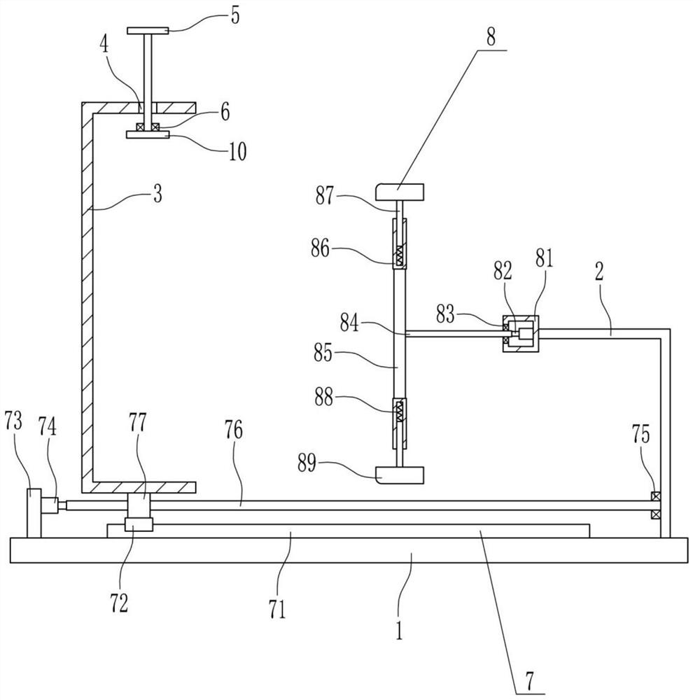
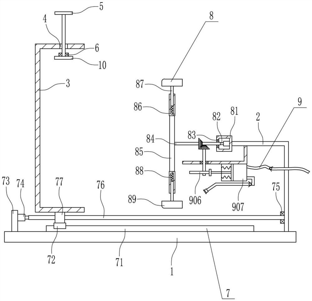
[0025] A kind of glue tank deglue equipment for LED lamp dispensing, such as Figure 1-4As shown, it includes a base plate 1, a 7-type plate 2, a u-placed frame 3, a T-shaped screw 5, a first bearing seat 6, a left and right moving device 7, a glue removal device 8 and a fixed plate 10. The top of the base plate 1 is equipped with left and right Mobile device 7, is connected with u placement frame 3 on the left and right mobile device 7, has screw hole 4 on the top of u placement type frame 3, is provided with T-shaped screw rod 5 movablely in screw hole 4, and is provided with fixed screw rod 5 below T-shaped screw rod 5. Plate 10, a first bearing seat 6 is installed on the top of the fixed plate 10, the bearing in the first bearing seat 6 is in interference connection with the bottom end of the T-shaped screw rod 5, and the right side of the top of the bottom plate 1 is connected with the 7-type plate 2 and the 7-type plate 2 Glue removing device 8 is installed on the left e...

Embodiment 2

[0027] A kind of glue tank deglue equipment for LED lamp dispensing, such as Figure 1-4 As shown, it includes a base plate 1, a 7-type plate 2, a u-placed frame 3, a T-shaped screw 5, a first bearing seat 6, a left and right moving device 7, a glue removal device 8 and a fixed plate 10. The top of the base plate 1 is equipped with left and right Mobile device 7, is connected with u placement frame 3 on the left and right mobile device 7, has screw hole 4 on the top of u placement type frame 3, is provided with T-shaped screw rod 5 movablely in screw hole 4, and is provided with fixed screw rod 5 below T-shaped screw rod 5. Plate 10, a first bearing seat 6 is installed on the top of the fixed plate 10, the bearing in the first bearing seat 6 is in interference connection with the bottom end of the T-shaped screw rod 5, and the right side of the top of the bottom plate 1 is connected with the 7-type plate 2 and the 7-type plate 2 Glue removing device 8 is installed on the left ...

Embodiment 3

[0030] A kind of glue tank deglue equipment for LED lamp dispensing, such as Figure 1-4 As shown, it includes a base plate 1, a 7-type plate 2, a u-placed frame 3, a T-shaped screw 5, a first bearing seat 6, a left and right moving device 7, a glue removal device 8 and a fixed plate 10. The top of the base plate 1 is equipped with left and right Mobile device 7, is connected with u placement frame 3 on the left and right mobile device 7, has screw hole 4 on the top of u placement type frame 3, is provided with T-shaped screw rod 5 movablely in screw hole 4, and is provided with fixed screw rod 5 below T-shaped screw rod 5. Plate 10, a first bearing seat 6 is installed on the top of the fixed plate 10, the bearing in the first bearing seat 6 is in interference connection with the bottom end of the T-shaped screw rod 5, and the right side of the top of the bottom plate 1 is connected with the 7-type plate 2 and the 7-type plate 2 Glue removing device 8 is installed on the left ...


PUM


Abstract

The invention relates to adhesive removal equipment, in particular to adhesive removal equipment for an adhesive tank for adhesive dispensing of LED lamps. In order to solve the technical problems, the adhesive removal equipment for the adhesive tank for adhesive dispensing of the LED lamps is provided, does not easily stain a hand with an adhesive and is comparatively convenient. The adhesive removal equipment for the adhesive tank for adhesive dispensing of the LED lamps comprises a bottom plate, a 7-shaped plate, a u-type storage frame, a T-type screw, a first bearing block, a leftward-rightward moving device and the like, wherein the leftward-rightward moving device is mounted at the top of the bottom plate, the u-type storage frame is connected to the leftward-rightward moving device,a screw hole is formed in the top of the u-type storage frame, the T-type screw is movably arranged in the screw hole, and a fixing plate is arranged below the T-type screw. Through cooperation of the leftward-rightward moving device and an adhesive removal device, the adhesive on the inner wall of the adhesive tank can be removed, manual adhesive removal is not required, the adhesive removal device can drive a liquid spraying device to work, the adhesive removal device can better remove the adhesive on the inner wall of the adhesive tank, so that the effects that the adhesive does not easilystain the hand and adhesive removal is comparatively convenient are realized.

Description

technical field [0001] The invention relates to a glue removing device, in particular to a glue removing device for a glue tank used for glue dispensing of an LED lamp. Background technique [0002] The LED lamp is an electroluminescent semiconductor material chip, which is cured on the bracket with silver glue or white glue, and then connected to the chip and the circuit board with silver or gold wires, and sealed with epoxy resin around it to protect the inner core wire. Function, the shell is finally installed, so the shock resistance of the LED lamp is good. [0003] During the production process of LED lights, it is necessary to dispense glue on the LED lights. After the glue is dispensed, part of the glue will remain on the inner wall of the glue tank. In order to facilitate the next use, people will remove the glue on the inner wall of the glue tank. When removing the glue on the inner wall, the glue is easy to get on people's hands, and the glue is relatively sticky...

Claims


Application Information

Patent Timeline
Patent Type & Authority Patents(China)
IPC IPC(8): B05B15/50
CPCB05B15/50B05C11/00
Inventor 李炳君李敏王佳
Owner 浙江罗丹照明电器有限公司
Why Eureka
Try Eureka