
Desktop air curtain power device

A power plant and air curtain technology, applied in the direction of shielding with air flow, piping arrangement, climate sustainability, etc., can solve the problems of reduced inhaled air quality, increased risk of cross-infection, increased public risk, etc.

Pending Publication Date: 2021-01-01
XI'AN UNIVERSITY OF ARCHITECTURE AND TECHNOLOGY
View PDF0 Cites 0 Cited by
  • Summary
  • Abstract
  • Description
  • Claims
  • Application Information

AI Technical Summary

Problems solved by technology

[0002] The virus is mainly transmitted from person to person by sick people coughing or sneezing in public places, but the fact that the public is at increased risk suggests that traditional indoor ventilation methods (mixing ventilation MV, displacement ventilation DV, etc.) may not be effective in protecting People are protected from respiratory diseases in offices and public places
[0003] Although traditional stratified ventilation methods, such as displacement ventilation, have a high ventilation coefficient, due to the existence of vertical temperature gradients, this will cause stratified exhalation in the working and living areas of personnel, which is the so-called concept of pollutant lock-up
Contaminants locked in the breathing zone greatly increase the risk of cross-infection
Not only that, the airflow reaching the breathing zone through the displacement ventilation system may also carry pollutants carried from low places such as the ground, which also reduces the quality of the inhaled air
[0004] However, in the existing office environment, the air supply system has been laid and put into use, and it would take too much time and effort to change and optimize the overall air supply system. Therefore, in order to reduce the infection probability of indoor respiratory diseases, a It is necessary to solve the above problems by means of

Method used


Image

  • Desktop air curtain power device
  • Desktop air curtain power device
  • Desktop air curtain power device

Examples


Embodiment Construction

[0031] The present invention is described in further detail below in conjunction with accompanying drawing:

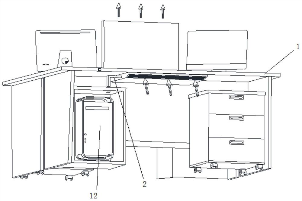
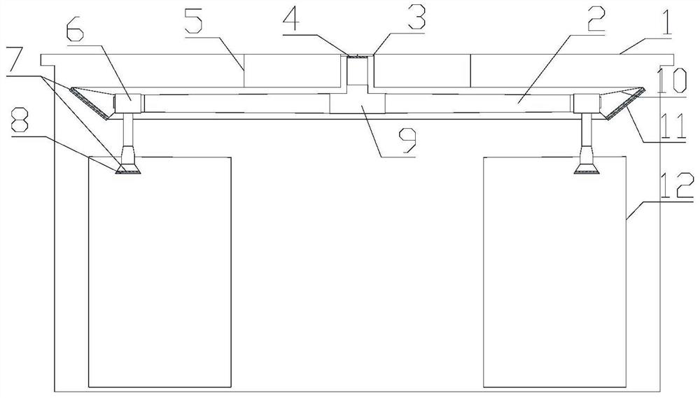
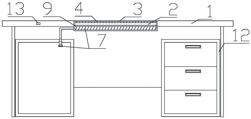
[0032] Such as Figure 1~4 As shown, the present invention discloses an air curtain power device for a desktop 1, comprising an air inlet duct arranged under the desktop 1, a fan 6 and a conveying duct 2, and an air outlet 4 provided on the desktop 1; An air inlet is provided, and the air inlet pipe is connected to the conveying pipe 2 through the fan 6, and the conveying pipe 2 is connected to the air outlet 4; a control switch 13 is provided on the desktop 1, and the control switch 13 is connected to the fan 6, and the control switch 13 is used to control The opening and closing of fan 6.

[0033] Specifically, the delivery pipeline 2 is fixedly installed under the tabletop 1 through the pipeline bracket 5 .

[0034] More preferably, a baffle 3 is hinged at the air outlet 4, and when the baffle 3 is closed, the baffle 3 covers the air outlet 4 to prevent pollutants...


PUM


Abstract

The invention belongs to the field of cross infection prevention, and particularly relates to a desktop air curtain power device. The device comprises an air inlet pipeline, a fan, a conveying pipeline and an air outlet, wherein the air inlet pipeline, the fan and the conveying pipeline are arranged below a desktop, and the air outlet is formed in the desktop; an air inlet is formed in the air inlet pipeline, the air inlet pipeline is connected with the conveying pipeline through the fan, the conveying pipeline is connected with the air outlet, and an air curtain is formed above the air outlet; and a control switch is arranged on the desktop, connected with the fan and used for controlling the startup and shutdown of the fan. According to the device, the fan conveys air flow to the conveying pipeline through the air inlet pipeline, the conveying pipeline sends out the air flow from the air outlet, and then the air curtain is formed; and the device is simple in structure and effectivelylowers the risk of cross infection on the basis of improving the quality of air inhaled by personnel under the condition of not changing an existing office building air supply system.

Description

technical field [0001] The invention belongs to the field of preventing cross-infection, and in particular relates to a desktop air curtain power device. Background technique [0002] The virus is mainly transmitted from person to person by sick people coughing or sneezing in public places, but the fact that the public is at increased risk suggests that traditional indoor ventilation methods (mixing ventilation MV, displacement ventilation DV, etc.) may not be effective in protecting People are protected from respiratory diseases in offices and public places. [0003] Although traditional stratified ventilation methods, such as displacement ventilation, have a high ventilation coefficient, due to the existence of vertical temperature gradients, this will cause stratified exhalation in the working and living areas of personnel, which is the so-called concept of pollutant lock-up. Contaminants locked in the breathing zone greatly increase the risk of cross-infection. Not onl...

Claims


Application Information

Patent Timeline
IPC IPC(8): F24F9/00F24F13/28F24F13/02F24F13/08F24F11/89
CPCF24F9/00F24F13/28F24F13/02F24F13/08F24F11/89Y02B30/70
Inventor 杨斌吴梦纯杨长青周斌苏伟高然尹海国李安桂
Owner XI'AN UNIVERSITY OF ARCHITECTURE AND TECHNOLOGY
Learn More