Neurological function rehabilitation training device and method
A technology for rehabilitation training and nerve function, applied in passive exercise equipment, physical therapy, etc., can solve problems such as ankle extrusion, injury, and inability to fix the calf, and achieve the guaranteed effect
- Summary
- Abstract
- Description
- Claims
- Application Information
AI Technical Summary
Problems solved by technology
Method used
Image
Examples
Embodiment 1
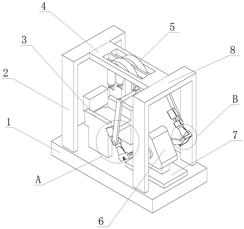
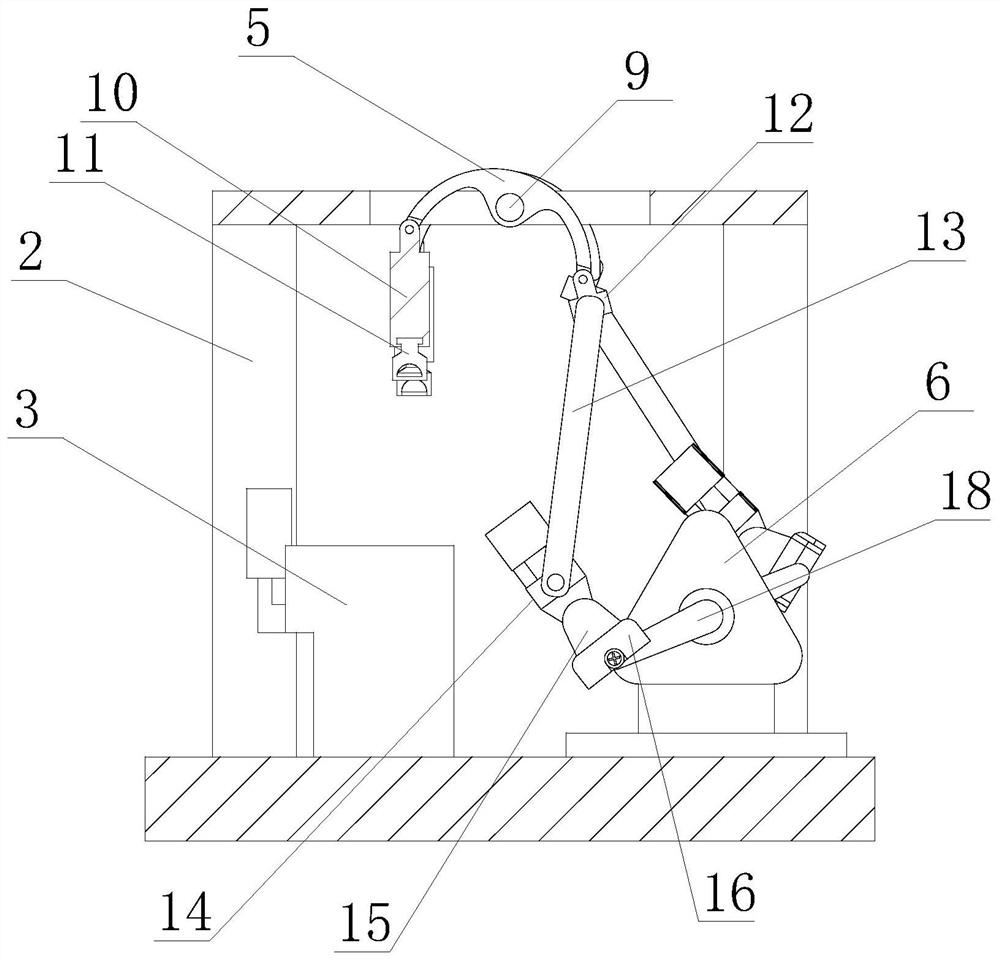
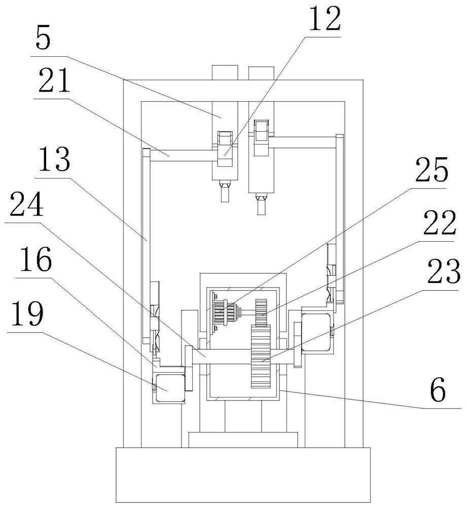
[0036] Such as Figure 1-Figure 8Shown, the first aspect, the present invention provides a kind of nerve function rehabilitation training device, comprises base 1, and the top of base 1 is provided with No. 1 door-shaped frame 2 and No. The bottom surface of No. door-shaped frame 8 is fixedly connected with the top of base 1, and connecting plate 4 is arranged between No. one door-shaped frame 2 and No. two door-shaped frame 8, and the two ends of connecting plate 4 are respectively connected with No. It is fixedly connected with the outer wall of the No. 2 door frame 8, and the top of the connecting plate 4 is provided with mutually symmetrical through grooves, and the middle part of the through groove of the connecting plate 4 is fixedly connected with a rotating shaft 9, and the outer wall of the rotating shaft 9 is movably connected with a rotating plate 5. The number of rotating plates 5 is set to two. The shape of the rotating plate 5 is C-shaped. The top of the base 1 i...
Embodiment 2
[0038] Such as Figure 1-6 As shown, on the basis of Embodiment 1, the present invention provides a technical solution: one side of the seat 3 is provided with a fixed plate 7, the bottom surface of the fixed plate 7 is fixedly connected with the top of the base 1, and the top of the seat 3 is arranged There is a power box 6, the bottom surface of the power box 6 is fixedly connected with the top of the fixed plate 7, the inside of the power box 6 is provided with a No. 2 fixed shaft 24, and the outer wall of the No. 2 fixed shaft 24 is rotatably connected with the inwall of the power box 6. The outer wall of the fixed shaft 24 is fixedly connected with the No. 2 gear 23, and the top of the No. 2 fixed shaft 24 is provided with a servo motor 25, and one side of the servo motor 25 is fixedly installed on the inner wall of the power box 6 by the mounting frame, so that the present invention can be used for the inability to When the patient who independently steps on the pedal 19...
Embodiment 3
[0040] Such as Figure 7-8 As shown, on the basis of Embodiment 1 and Embodiment 2, the present invention provides a technical solution: preferably, the side of the pedal 19 away from the fixed rod 18 is provided with a pedal connecting block 16, and the pedal connecting block 16 One side is fixedly connected with mutually symmetrical insertion plates 30, and the outer wall of the pedal 19 is provided with mutually symmetrical insertion grooves 31, and the outer wall of the insertion plate 30 is movably connected with the inner wall of the insertion groove 31, and the two ends of the pedal connecting block 16 are provided with Movable plate 27, one end of movable plate 27 is fixedly connected with movable pull rod 29, and the outer wall of movable pull rod 29 is movably connected with the inwall of pedal connection block 16, and the outer wall of movable pull rod 29 is movably connected with spring 28, so that pedal connection block 16 can be pulled The movable plate 27 drives...
PUM
 Abstract
Description
Claims
Application Information
 - R&D
- Intellectual Property
- Life Sciences
- Materials
- Tech Scout
- Unparalleled Data Quality
- Higher Quality Content
- 60% Fewer Hallucinations
Browse by: Latest US Patents, China's latest patents, Technical Efficacy Thesaurus, Application Domain, Technology Topic, Popular Technical Reports.
© 2025 PatSnap. All rights reserved.Legal|Privacy policy|Modern Slavery Act Transparency Statement|Sitemap|About US| Contact US: help@patsnap.com


