Exercise bicycle and seat adjusting device thereof

An adjustment device, a bicycle technology, applied in the directions of training equipment for adjusting coordination, training equipment for adjusting cardiovascular system, sports accessories, etc., can solve the problems of low practicability, complicated operation, inconvenient use, etc. Convenience, simplification of operation steps, and the effect of improving practicability

Inactive Publication Date: 2021-01-05
江苏福维健康科技有限公司
6 Cites 1 Cited by

AI-Extracted Technical Summary

Problems solved by technology

[0004] In order to adapt to the use of people of different heights, the existing indoor exercise bike needs to have the seat with an adjustment function, and the seat is usually fixed by a hoop to the sleeve for installing the seat when the seat is adjusted, and the hoop is used to The threaded rod is fixed. When adjusting, you need to rotate the threaded rod, loosen the hoop and then adjust the seat. After the adjustment, you have to tighten the threa...

Abstract

The invention discloses an exercise bicycle and a seat adjusting device thereof, and relates to fitness equipment; in particular, the exercise bicycle comprises an exercise bicycle frame, a seat and an adjusting device for adjusting the position of the seat. In the implementation process, compared with the mode that a traditional fitness bicycle can only be adjusted in the height direction, according to the technical scheme, the front-back position of the seat can be adjusted, the exercise bicycle can better adapt to people with different use habits, and the practicability of the exercise bicycle is effectively improved; when the height of the seat is adjusted, a second clamping block is pulled out through a pull ring to be separated from an adjusting vertical rod, the position of the adjusting vertical rod in the vertical direction can be adjusted; and compared with a threaded adjusting mode in a traditional mode, the exercise bicycle is obviously more convenient and faster to operate, simplifies operation steps when a user adjusts the seat, and is convenient to use and high in practicability. And the adjusting vertical rod can be fixed in a buckling mode, the fixing effect is good, and the situation that the seat slides off is avoided.

Application Domain

Muscle exercising devicesMovement coordination devices +1

Technology Topic

Vehicle framePhysical therapy +1

Image

  • Exercise bicycle and seat adjusting device thereof
  • Exercise bicycle and seat adjusting device thereof
  • Exercise bicycle and seat adjusting device thereof

Examples

  • Experimental program(1)

Example Embodiment

[0025] The following will clearly and completely describe the technical solutions in the embodiments of the present invention with reference to the accompanying drawings in the embodiments of the present invention. Obviously, the described embodiments are only some, not all, embodiments of the present invention. Based on the embodiments of the present invention, all other embodiments obtained by persons of ordinary skill in the art without making creative efforts belong to the protection scope of the present invention.
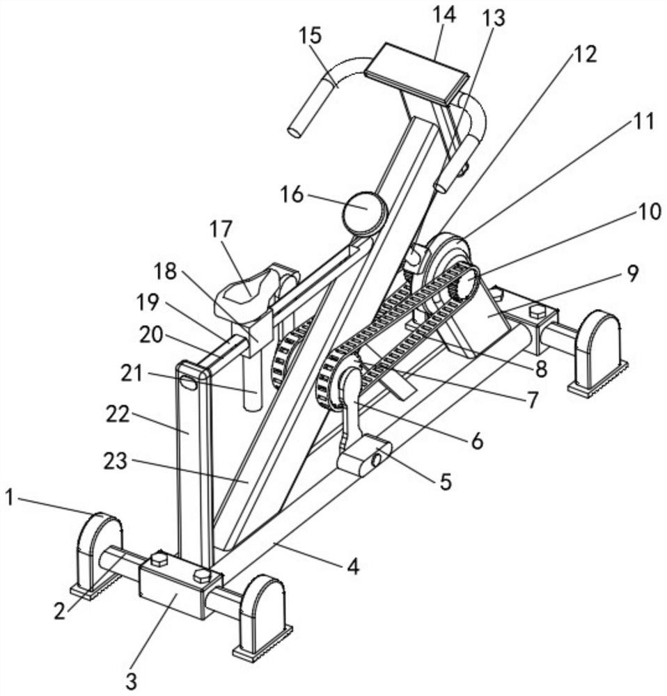
[0026] see figure 1 , in an embodiment of the present invention, an exercise bicycle includes a frame of an exercise bicycle, a seat 17 and an adjusting device for adjusting the position of the seat 17, the frame includes a horizontally installed bottom cross bar 4 and The fixed block 3 welded on both ends of the bottom cross bar 4, the fixed block 3 is fixed and installed in the middle of the horizontally arranged connecting rod 2 by bolts, the connecting rod 2 and the bottom cross bar 4 are perpendicular to each other, and the two ends of the connecting rod 2 are welded with supports Foot 1, the bottom surface of the supporting foot 1 is fixed with a rubber pad for protecting the cement floor by glue.
[0027] One end of the bottom cross bar 4 is welded with a mounting seat 9, and the top of the mounting seat 9 is provided with a groove, and a counterweight wheel 11 is installed in the groove through the rotation of the rotating shaft, and the two ends of the rotating shaft used to connect the breeding wheel 11 all protrude The pinion 10 is welded on the outside of the mounting base 9, the other end of the bottom cross bar 4 is welded with an inclined diagonal brace 23, and a reinforcing rib for improving the mechanical strength of the diagonal brace 23 is welded between the diagonal brace 23 and the bottom cross bar 4 , the middle part of the diagonal bracket 23 is rotatably equipped with a connecting shaft, the two ends of the connecting shaft are welded with a large gear 7 and the large gear 7 is symmetrically arranged with respect to the diagonal bracket 23, and the large gear 7 and the pinion 10 are connected by a rack 8 , the two ends of the connecting shaft for installing the large gear 7 are welded with a vertical connecting plate 6, and the ends of the connecting plate 6 are rotated and installed with a pedal 5 through a fixed pin, and the pedal 5 is symmetrical about the diagonal brace 23 Reversely set, thus constitute the pedal structure of the bicycle.
[0028] Adjusting rod 13 is threadedly connected on the diagonal brace 23, the bottom end of adjusting rod 13 faces the weight wheel 11 and is fixedly equipped with brake pads 12 by bolts, and the top end of adjusting rod 13 is welded with adjusting disc 16. When in use, The adjustment lever 13 is rotated by the adjustment disc 16, and the adjustment lever 13 interacts with the diagonal brace 23 to adjust the pressure between the brake pad 12 and the weight wheel 11, thereby adjusting the strength of the bodybuilder when using the exercise bike.
[0029] The top of the diagonal bracket 23 is fixed with a display screen 14 and a handle 15 by bolts. It should be noted that a pressure sensor is clamped and fixed between the brake pad 12 and the adjustment rod 13, and the built-in pressure sensor and the display screen 14 The processor is electrically connected, so that the pressure data between the brake pads 12 and the weight wheel 11 is intuitively displayed on the display screen 14, which is convenient for the user to adjust the weight of the weight wheel 11 more accurately.
[0030] Described adjusting device comprises the support frame 22 that is installed on the other end of bottom cross bar 4 and the adjustment cross bar 20 of horizontal installation, and the bottom end of described support frame 22 is welded on the other end of bottom cross bar 4, and the top of support frame 22 and One end of the horizontally installed adjusting cross bar 20 is fixedly connected, and the other end of the adjusting cross bar 20 is fixedly connected with the diagonal brace 23. The adjusting cross bar 23 is slidably equipped with a slide block 18, and the slide block 18 is slidably installed with a vertical adjustment The vertical bar 21 and the adjusting cross bar 23 are provided with a chute 19 for adjusting the vertical bar 21 to slide, and the seat 17 is fixed on the top of the adjusting vertical bar 21 by bolts.
[0031] see figure 2 One side of the slider 18 is welded with an adjustment frame 29, and a horizontal sliding plate 26 is slidably installed in the adjustment frame 29, and both ends of the sliding plate 26 extend out of the adjustment frame 29 and are integrally formed and fixed with a first block 25 The outer wall of the adjusting cross bar 20 is uniformly provided with a plurality of first draw-in slots 24 matching the first block 25, the middle part of the connecting plate 26 is connected with one end of the screw rod 28 in rotation, and the screw rod 28 is connected with the adjusting frame 29. The middle part is threaded and the other end of the screw mandrel 28 is stretched out and welded with a rotating disk 27 outside the adjustment frame 29 .
[0032]It should be noted that the screw rod 28 is rotated by the turntable 27, the screw rod 28 interacts with the adjustment frame 29 to adjust the position of the connecting plate 26, and the connecting plate 26 drives the first block 25 to be inserted into the slot 24, thereby The position of the slider 18 is fixed; compared with the traditional exercise bike that can only be adjusted in the height direction, this technical solution can adjust the front and rear positions of the seat during use, so as to better adapt to different usage habits The crowd effectively improves the practicability of the exercise bike.
[0033] see image 3 One end of the upper surface of the slider 18 is welded with a guide block 32, a horizontal second block 31 is installed on the guide block 32, and a plurality of horizontal blocks 31 are evenly provided on the side of the adjustment vertical bar 21 corresponding to the second block 31. The second clamping slot 30 matched with the second clamping block 31, one end of the second clamping block 31 is inserted into the second clamping block 31, thereby fixing the height of the vertical rod 21 for adjustment, the other end of the second clamping block 31 A draw ring 34 is welded, the side of the draw ring 34 is fixedly connected to one end of the spring 33 , and the other end of the spring 33 is fixedly connected to the side of the fixed block 32 .
[0034] It should be noted that when adjusting the height of the seat, the second block 31 is pulled out and separated from the adjustment vertical bar 21 through the pull ring 34, so that the vertical position of the adjustment vertical bar 21 can be adjusted. Compared with the traditional method of thread adjustment, the operation of this technical solution is obviously more convenient and quicker, which simplifies the operation steps of the user when adjusting, and is easy to use, and the adjustment vertical rod is fixed by the buckle, and the fixing effect is excellent. Well, there is no chance of the seat slipping off.
[0035] Although the present invention has been described in detail with reference to the aforementioned embodiments, those skilled in the art can still modify the technical solutions described in the aforementioned embodiments, or perform equivalent replacements for some of the technical features. Within the spirit and principles of the present invention, any modifications, equivalent replacements, improvements, etc., should be included within the protection scope of the present invention, and the content that is not described in detail in this specification belongs to those skilled in the art. existing technology.

PUM

no PUM

Description & Claims & Application Information

We can also present the details of the Description, Claims and Application information to help users get a comprehensive understanding of the technical details of the patent, such as background art, summary of invention, brief description of drawings, description of embodiments, and other original content. On the other hand, users can also determine the specific scope of protection of the technology through the list of claims; as well as understand the changes in the life cycle of the technology with the presentation of the patent timeline. Login to view more.

Similar technology patents

Crop transplanter

Owner:肥东县爱雯家庭农场

Television bracket

InactiveCN102691862AEasy to fix the cameraImprove practicality
Owner:SUZHOU QINGDING PRECISION MACHINERY PROD

Environmentally-friendly textile machine with functions of shock absorption and cotton flock absorption

PendingCN107575718AImprove practicalityAvoid excessive vibration
Owner:长兴宝诺纺织科技有限公司

Processing method and equipment of electronic health service

InactiveCN104715128AImprove practicality
Owner:CHINA MOBILE COMM GRP CO LTD

Video information indication method and set-top box

InactiveCN101321255AImprove practicality
Owner:CHINA UNITED NETWORK COMM GRP CO LTD

Classification and recommendation of technical efficacy words

  • Improve practicality
  • easy to operate

Device and method for constructing self-adaptive graphic user interface (GUI)

ActiveCN102193786ASolve control intersection and information truncation problemsImprove practicality
Owner:INDUSTRIAL AND COMMERCIAL BANK OF CHINA

Photographing method and terminal

Owner:GUANGDONG OPPO MOBILE TELECOMM CORP LTD

Lancet device

InactiveUS7303573B2inexpensively mass-producedeasy to operate
Owner:ABBOTT DIABETES CARE INC

Rapid and non-invasive optical detection of internal bleeding

InactiveUS20050065436A1easy to operaterapid and accurate result
Owner:HO WINSTON ZONH +2
Why Eureka
Try Eureka