Adjustable-pressure type pressure-stabilizing nozzle

A type-adjusting and voltage-stabilizing technology, applied in the direction of injection device, liquid injection device, etc., can solve the problems of pressure change, affecting the nozzle, and unstable ejection flow, and achieve the effect of automatic and precise adjustment of the injection pressure ratio.

Active Publication Date: 2021-01-05
ANHUI UNIVERSITY OF TECHNOLOGY AND SCIENCE
View PDF8 Cites 6 Cited by
  • Summary
  • Abstract
  • Description
  • Claims
  • Application Information

AI Technical Summary

Problems solved by technology

[0002] Nozzles can be roughly divided into spray nozzles, fuel nozzles, sandblasting nozzles, watering nozzles, etc. according to their functions. Usually, the pressure of the nozzles comes from the pressure of the high-pressure liquid in the pipeline connecting the nozzles, so when the unstable high-pressure liquid enters the nozzle When the nozzle itself cannot be self-regulated, this will cause the instability and unbalance of the liquid flow rate. When the unstable high-pressure liquid is sent into the nozzle, there will be a significant change in pressure, which will affect the quality of the jet flow of the nozzle and the ejection flow rate. extremely unstable

Method used


Image

  • Adjustable-pressure type pressure-stabilizing nozzle
  • Adjustable-pressure type pressure-stabilizing nozzle
  • Adjustable-pressure type pressure-stabilizing nozzle

Examples


Embodiment Construction

[0035] In order to make the above objects, features and advantages of the present invention more comprehensible, specific implementations of the present invention will be described in detail below in conjunction with the accompanying drawings. In the following description, numerous specific details are set forth in order to provide a thorough understanding of the present invention. However, the present invention can be implemented in many other ways different from those described here, and those skilled in the art can make similar improvements without departing from the connotation of the present invention, so the present invention is not limited by the specific embodiments disclosed below.

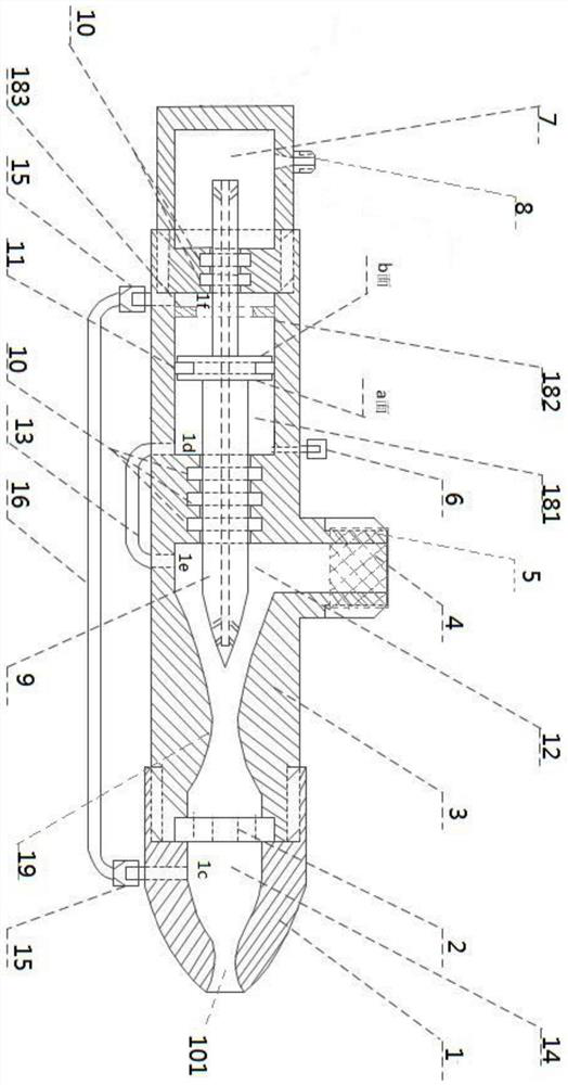
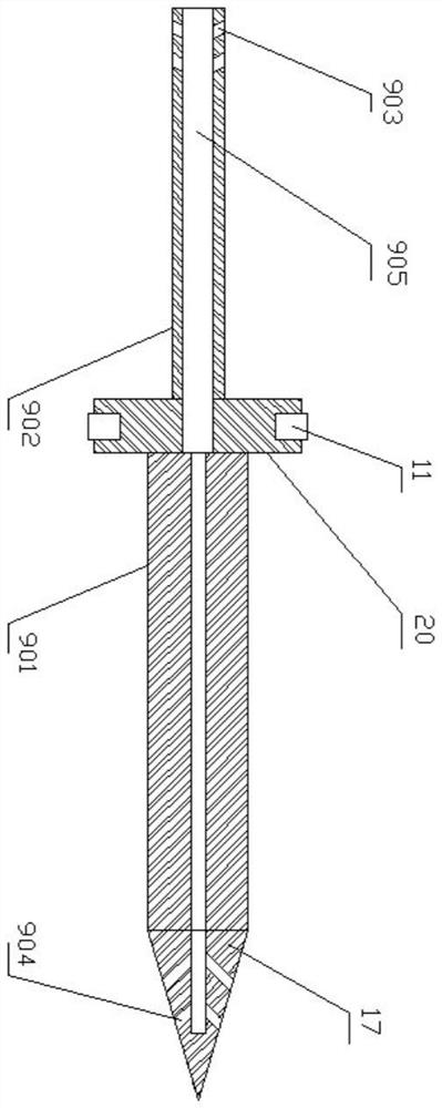
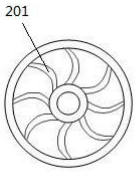
[0036] see Figure 1 to Figure 4 , a pressure-adjustable pressure-stabilized fuel nozzle, including a casing 3, a fuel supply interface 4 formed by the casing 3, and a nozzle 1, and the casing 3 also forms a rectifying chamber 14 communicating with the nozzle 1 and communicating with all ...


PUM


Abstract

The invention discloses an adjustable-pressure type pressure-stabilizing nozzle, and relates to the technical field of nozzles. The adjustable-pressure type pressure-stabilizing nozzle comprises a shell, a liquid supply joint and a spraying head, wherein the liquid supply joint and the spraying head are formed by the shell; a rectifying chamber which communicates with the spraying head and a liquid inlet chamber which communicates with the liquid supply joint are also formed by the shell; a diameter-varied pipe section which has a structure of a contracted middle part and expanded front and rear parts and is formed by the shell is positioned between the liquid inlet chamber and the rectifying chamber which is arranged at the front end of the liquid inlet chamber; the shell is equipped witha separate pressure regulation chamber which is formed in the rear part of the liquid inlet chamber; the nozzle also comprises the shell which penetrates through the pressure regulation chamber and the liquid inlet chamber as well as between the pressure regulation chamber and the liquid inlet chamber, and a control rod which finally extends to the junction of the diameter-varied pipe section andthe liquid inlet chamber; and the control rod can be moved back and forth in the shell, and a pressure regulation process and a pressure stabilizing process of the nozzle can be realized through front and back movement of the control rod. The adjustable-pressure type pressure-stabilizing nozzle disclosed by the invention has a function of accurately regulating an ejection pressure ratio, and canensure that the pressure of flow filed in the nozzle is stable and can be regulated, so that the stability of the ejection flow of the nozzle is improved; and moreover, the nozzle also has an atomization enhancement function, and thus, the working quality of jet flow is improved.

Description

technical field [0001] The invention relates to the technical field of nozzle manufacturing, in particular to a pressure-adjustable pressure-stabilizing nozzle. Background technique [0002] Nozzles can be roughly divided into spray nozzles, fuel nozzles, sandblasting nozzles, watering nozzles, etc. according to their functions. Usually, the pressure of the nozzles comes from the pressure of the high-pressure liquid in the pipeline connecting the nozzles, so when the unstable high-pressure liquid enters the nozzle When the nozzle itself cannot be self-regulated, this will cause the instability and unbalance of the liquid flow rate. When the unstable high-pressure liquid is sent into the nozzle, there will be a significant change in pressure, which will affect the quality of the jet flow of the nozzle and the ejection flow rate. Extremely unstable. [0003] In order to solve this problem, it is usually possible to improve the working efficiency of the jet nozzle by adjusting...

Claims


Application Information

Patent Timeline
Patent Type & Authority Applications(China)
IPC IPC(8): B05B7/04B05B7/12B05B12/08B05B15/16
CPCB05B7/0416B05B7/12B05B12/088B05B15/16
Inventor 高清振高菲秦广虎潘家保张荣芸潘道远肖平
Owner ANHUI UNIVERSITY OF TECHNOLOGY AND SCIENCE
Why Eureka
Try Eureka