Ultrasonic cleaning equipment with high safety

A technology for cleaning equipment and ultrasonic waves, which is applied in the directions of cleaning methods using liquids, cleaning methods and utensils, chemical instruments and methods, etc. Effect

Inactive Publication Date: 2021-01-05
陕西诺盈自动化仪表有限公司
View PDF1 Cites 0 Cited by
  • Summary
  • Abstract
  • Description
  • Claims
  • Application Information

AI Technical Summary

Problems solved by technology

[0006] The purpose of the present invention is to solve the problem in the prior art that not only it is inconvenient to fix the items to be cleaned, but also it is inconvenient to take the items, and a high-safety ultrasonic cleaning equipment is proposed

Method used


Image

  • Ultrasonic cleaning equipment with high safety
  • Ultrasonic cleaning equipment with high safety

Examples


Embodiment 1

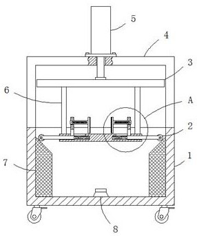
[0022] Example 1 as figure 1 As shown, this kind of high-safety ultrasonic cleaning equipment includes a box body 1 with an opening at the upper end. The baffle plate 3 matched with the opening of the U-shaped plate 4 is fixed with an electric push rod 5 in the upper middle of the horizontal part of the U-shaped plate 4. Fixedly connected, the inside of the opening of the box body 1 is provided with a horizontal supporting plate 9, and a vertical connecting plate 6 is symmetrically fixedly connected between the left and right sides of the upper end of the supporting plate 9 and the lower end of the baffle plate 3, and the inside of the box body 1 is located The left and right sides of the supporting plate 9 are symmetrically provided with rectangular blocks 7, and the side walls of the opposite sides of the two rectangular blocks 7 are fixedly connected with the inner side walls of the box body 1, and the opposite sides of the two rectangular blocks 7 The upper ends of the si...

Embodiment 2

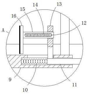
[0023] Embodiment 2 is on the basis of embodiment 1 such as figure 2 As shown, its moving mechanism includes a push rod 11 and a first spring 10, the rod wall of the push rod 11 is slidably connected with the hole wall of the blind hole, and one end of the push rod 11 extends to the outside of the blind hole and abuts against the inclined surface, the second Two ends of a spring 10 are respectively fixedly connected with one end of the push rod 11 located in the blind hole and the bottom of the blind hole, and the lower end of the movable plate 13 is fixedly connected with the upper side wall of the push rod 11 .

Embodiment 3

[0024] Embodiment 3 is such as on the basis of embodiment 1 figure 2 As shown, its clamping mechanism comprises movable rod 15, fixed rod 12, second spring 14 and splint 16, and the rod wall of movable rod 15 is slidably connected with the hole wall of slide hole, and the two ends of movable rod 15 all extend to Outside the sliding hole, the front side wall of the movable rod 15 is provided with a second strip hole, and the fixed rod 12 is longitudinally arranged in the inside of the second strip hole, and the front and rear ends of the fixed rod 12 are fixed to the wall of the sliding hole. Connect, the two ends of the second spring 14 are respectively fixedly connected with the left side wall of the fixed rod 12 and the left side hole wall of the second strip hole, and the clamping plate 16 is vertically fixed with one end of the movable rod 15 near the electric push rod 5 connect.


PUM


Abstract

The invention relates to the technical field of cleaning equipment, and discloses ultrasonic cleaning equipment with high safety. The equipment comprises a box body with an opening formed in the upperend, a U-shaped plate is fixedly connected to the upper end of the box body, a baffle matched with the opening of the box body is arranged on the upper side of the interior of the U-shaped plate, andan electric push rod is fixedly arranged in the middle of the upper end of the horizontal part of the U-shaped plate. The output end of the electric push rod penetrates through the upper end of the horizontal part of the U-shaped plate and is fixedly connected with the middle of the upper end of the baffle, a horizontal supporting plate is arranged in the opening of the box body, and vertical connecting plates are symmetrically and fixedly connected between the left side and the right side of the upper end of the supporting plate and the lower end of the baffle. Rectangular blocks are symmetrically arranged in the box body and located on the left side and the right side of the supporting plate. The side walls of the sides, deviating from each other, of the two rectangular blocks are fixedly connected with the inner side wall of the box body. According to the ultrasonic cleaning equipment with high safety, objects are convenient to take while the safety is high, and the to-be-cleaned objects can be automatically fixed.

Description

technical field [0001] The invention relates to the technical field of cleaning equipment, in particular to an ultrasonic cleaning equipment with high safety. Background technique [0002] At present, cleaning devices are often used in production and life, which can reduce manual output. It is a clear device commonly used in efficient and safe ultrasonic cleaning equipment. When the ultrasonic wave propagates in the liquid, its sound pressure changes drastically, causing strong cavitation and emulsification of the liquid. At this time, millions of tiny cavitations are generated in the liquid every second. bubble. These bubbles are rapidly produced in large quantities under the action of sound pressure, and continue to explode violently, resulting in strong impact and negative pressure suction, resulting in the peeling off of dirt. [0003] The existing high-safety ultrasonic cleaning equipment is not only inconvenient to fix the items to be cleaned during use, but also inc...

Claims


Application Information

Patent Timeline
Patent Type & Authority Applications(China)
IPC IPC(8): B08B3/12B08B13/00
CPCB08B3/12B08B13/00
Inventor 李军荣
Owner 陕西诺盈自动化仪表有限公司
Why Eureka
Try Eureka