Multifunctional subway seat for urban rail transit
A multifunctional technology for urban rail transit, applied in the field of multifunctional subway seats for urban rail transit, can solve the problems of poor practicability, no upgrade function, inconvenient carrying luggage and passengers with children, etc., to relieve fatigue sense, increase the effect of comfort
- Summary
- Abstract
- Description
- Claims
- Application Information
AI Technical Summary
Problems solved by technology
Method used
Image
Examples
Embodiment 1
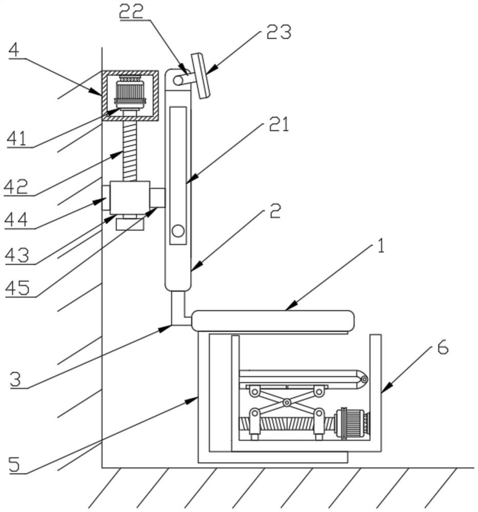
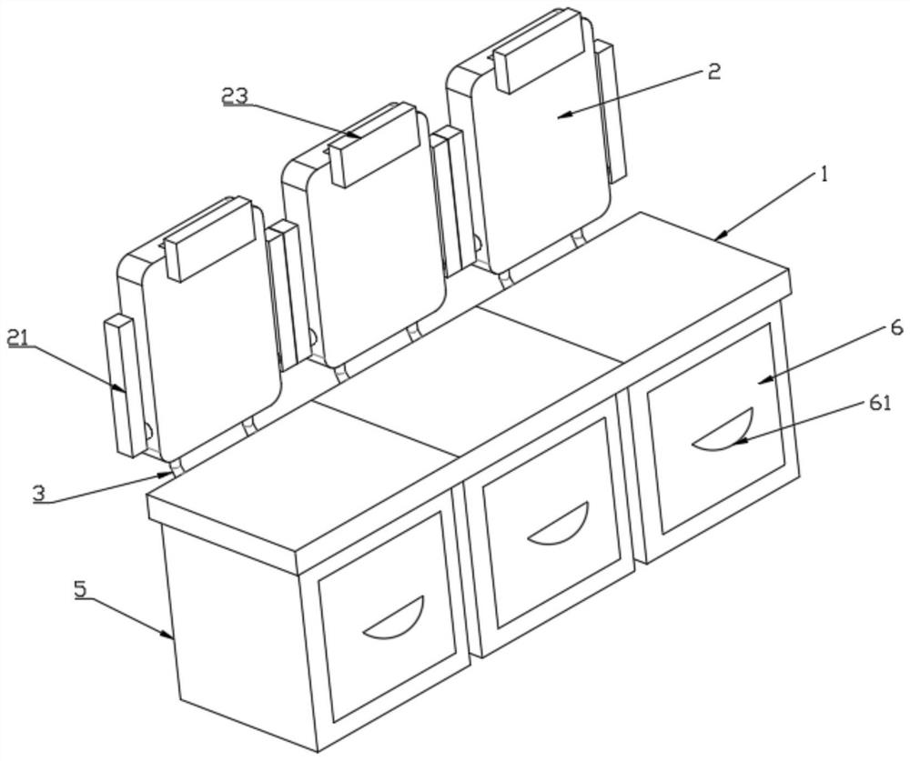
[0025] see Figure 1-3 , a multifunctional subway seat for urban rail transit, comprising a seat body, the seat body including a seat plate 1 and a back plate 2, and an L-shaped fixing rod is passed between the seat plate 1 and the back plate 2 3 fixedly connected; a motor protection box 4 is fixedly connected to the inner bulkhead of the subway, and a first motor 41 is fixedly connected in the motor protection box 4, and the output shaft of the first motor 41 runs through the inside of the motor protection box 4 and Fixedly connected with a single-rotation lead screw 42, the outer surface of the single-rotation lead screw 42 is threaded with a first threaded sleeve 43, and the side of the first threaded sleeve 43 close to the inner bulkhead of the subway is fixedly connected with a second threaded sleeve. A slide block 44, the first slide block 44 is slidingly connected with the inner bulkhead of the subway, and the side of the first threaded sleeve 43 away from the first sli...
Embodiment 2
[0029] This embodiment is a further improvement made on the basis of Embodiment 1, specifically as follows:
[0030] see Figure 1-3 , the bottom surface of the seat plate 1 is fixedly connected with a storage box 5, the front side of the storage box 5 is open, and the storage box 5 is slidably connected with a drawer 6, and a child seat is arranged in the drawer 6, and the child seat Driven by lifting mechanism.
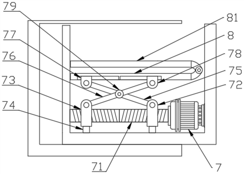
[0031] The lifting mechanism includes a second motor 7, a double-rotation lead screw 71, a second threaded sleeve 72, a third threaded sleeve 73, a second slider 74, a first connecting rod 75, a second connecting rod 76, a second A hinge 77 and a second hinge 78, the bottom end of the inner cavity of the drawer 6 is fixedly connected with the second motor 7, the output shaft of the second motor 7 is fixedly connected with the double-rotation lead screw 71, the The end of the double-rotation lead screw 71 away from the second motor 7 is rotatably connected to the s...
PUM
 Abstract
Description
Claims
Application Information
 - R&D
- Intellectual Property
- Life Sciences
- Materials
- Tech Scout
- Unparalleled Data Quality
- Higher Quality Content
- 60% Fewer Hallucinations
Browse by: Latest US Patents, China's latest patents, Technical Efficacy Thesaurus, Application Domain, Technology Topic, Popular Technical Reports.
© 2025 PatSnap. All rights reserved.Legal|Privacy policy|Modern Slavery Act Transparency Statement|Sitemap|About US| Contact US: help@patsnap.com


