Slider-crank mechanism capable of controlling and balancing inertia force

A technology of slider crank mechanism and inertial force, which is applied to mechanical equipment, belts/chains/gears, transmission devices, etc., and can solve problems such as the displacement of the slider crank mechanism and the inability to perform preliminary buffering

Active Publication Date: 2021-01-05
青岛理工大学(临沂)管理委员会办公室
View PDF6 Cites 1 Cited by
  • Summary
  • Abstract
  • Description
  • Claims
  • Application Information

AI Technical Summary

Problems solved by technology

[0005] In order to solve the above technical problems, the present invention provides a slider crank mechanism that can control the balance inertial force to solve the problem that when the existing slider crank mechanism needs to be controlled to stop in a balanced vertical state when the existing slider crank mechanism is in use, Due to the rotation

Method used


Image

  • Slider-crank mechanism capable of controlling and balancing inertia force
  • Slider-crank mechanism capable of controlling and balancing inertia force
  • Slider-crank mechanism capable of controlling and balancing inertia force

Examples


Embodiment

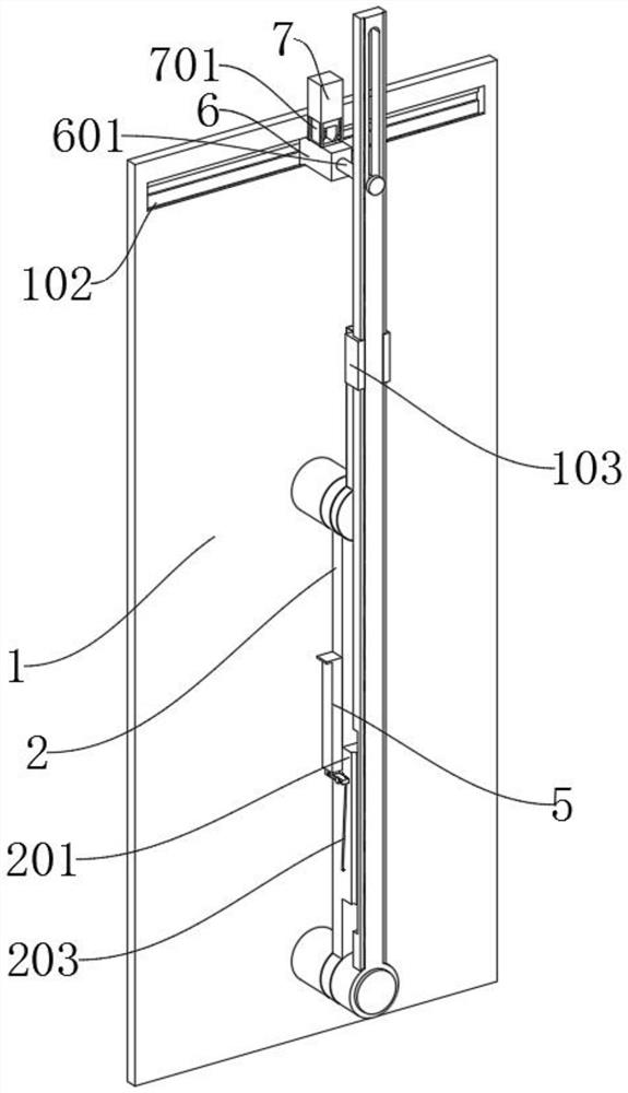
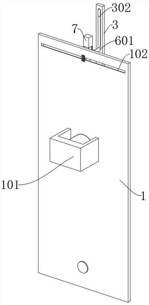
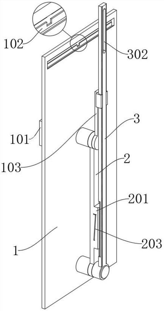
[0035] as attached figure 1 to attach Figure 9 Shown:

[0036] The invention provides a slider crank mechanism capable of controlling the balance inertial force, comprising a main body 1, a main shaft 2, a swing arm 3, a clip 4, an electric cylinder one 5, a moving block 6 and an electric cylinder two 7; the main body 1 is a rectangular plate structure, and the upper and lower ends of the main body 1 are provided with two installation holes, and the installation hole at the bottom is provided with a connecting shaft; the bottom of the swing arm 3 is provided with a connecting ring, and the connecting ring is sleeved on the outside of the connecting shaft; the electric cylinder One 5 is fixedly installed on both sides of the main shaft 2, and the bottom groove 502 at the bottom of the electric cylinder one 5 is inserted into the outer end of the moving rod 403; the moving block 6 is embedded in the top groove 102, and the front end of the moving block 6 The connecting rod 60...


PUM


Abstract

The invention provides a slider-crank mechanism capable of controlling and balancing inertia force, and relates to the technical field of slider-cranks. The mechanism aims to solve the problem that when an existing slider-crank mechanism is used, and a slider-crank needs to be controlled to stop in a balanced vertical state, due to the rotation inertia force of the slider-crank, displacement is generated after the slider-crank mechanism stops. The novel mechanism comprises a main body and a main shaft, wherein the main body is of a rectangular plate-shaped structure, and two mounting holes areformed in the upper end and the lower end of the main body. The novel mechanism is characterized in that the main shaft is used for being arranged between an overturning arm and a swing arm, when a slider-crank rotates, the slider-crank needs to be stopped in a vertical state, and inertia force cannot be generated, a first electric cylinder can be directly controlled to ascend through a switch sothat limiting of a clamping piece can be removed, and the clamping piece can be in the state of being supported outwards by a spring; and when the swing arm rotates to a vertical state, the clampingpiece can be compressed firstly and then pushed by the spring to move outwards, and then the clamping piece is effectively inserted into a clamping groove.

Description

technical field [0001] The invention belongs to the technical field of the slider crank, and more specifically relates to a slider crank mechanism capable of controlling the balance inertial force. Background technique [0002] The crank-slider mechanism refers to a planar linkage mechanism that uses a crank and a slider to achieve mutual conversion between rotation and movement. In the crank-slider mechanism, the component that forms a moving pair with the frame is a slider. The components are connecting rods. [0003] For example, the application number: CN200810018388.2 relates to a method for balancing the inertial force of the crank-link slider mechanism of a high-speed punch press, including revealing the mechanism of the inertial force generated by the crank-link slider mechanism. Based on the fully symmetrical crank-link slider mechanism of one-point or four-point double cranks, the calculation formula for the accurate balance mass of the large gear eccentric block ...

Claims


Application Information

Patent Timeline
IPC IPC(8): F16H21/18F16H21/06
CPCF16H21/06F16H21/18
Inventor 魏云玲李杨任付娥李晓刚刘建泽
Owner 青岛理工大学(临沂)管理委员会办公室
Why Eureka
Try Eureka