
Ceramic valve core capable of realizing rapid rotary positioning

A ceramic valve core and fast technology, applied in the field of ceramic valve core, can solve the problems of ice extrusion damage, easy freezing, and affecting the service life of ceramic valves, so as to improve reliability, ensure stability, and improve convenience Effect

Active Publication Date: 2021-01-05
SHANGHAI GEAR PLASTIC
View PDF6 Cites 0 Cited by
  • Summary
  • Abstract
  • Description
  • Claims
  • Application Information

AI Technical Summary

Problems solved by technology

[0005] Aiming at the deficiencies of the prior art, the present invention provides a ceramic valve core capable of fast rotation and positioning, which can effectively improve the convenience of disassembling and assembling the ceramic valve core At the same time, it can ensure the stability of the connection of the bottom cover of the ceramic valve core, and can improve the reliability of the ceramic valve core, and can also effectively protect the protection ability of the ceramic valve core, so that it has an antifreeze function and improves the safety of the ceramic valve core. And convenience, while ensuring the service life of the ceramic valve core, and realizing the advantages of the ceramic valve core being able to rotate quickly, it solves the problem that the connecting buckle of the ceramic valve bottom cover is easy to wear after repeated disassembly and assembly, resulting in an unstable connection of the bottom cover The situation will affect the normal use of ceramic valves, and affect the reliability of the ceramic valve core, and the protection ability of ceramic valves is poor, especially in cold winter nights, it is easy to be frozen, or even squeezed by ice cubes, thus affecting ceramic valves. The problem of valve service life

Method used


Image

  • Ceramic valve core capable of realizing rapid rotary positioning
  • Ceramic valve core capable of realizing rapid rotary positioning
  • Ceramic valve core capable of realizing rapid rotary positioning

Examples


Embodiment Construction

[0023] The technical solutions in the embodiments of the present invention will be clearly and completely described below. Obviously, the described embodiments are only some of the embodiments of the present invention, but not all of them. Based on the embodiments of the present invention, all other embodiments obtained by persons of ordinary skill in the art without making creative efforts belong to the protection scope of the present invention.

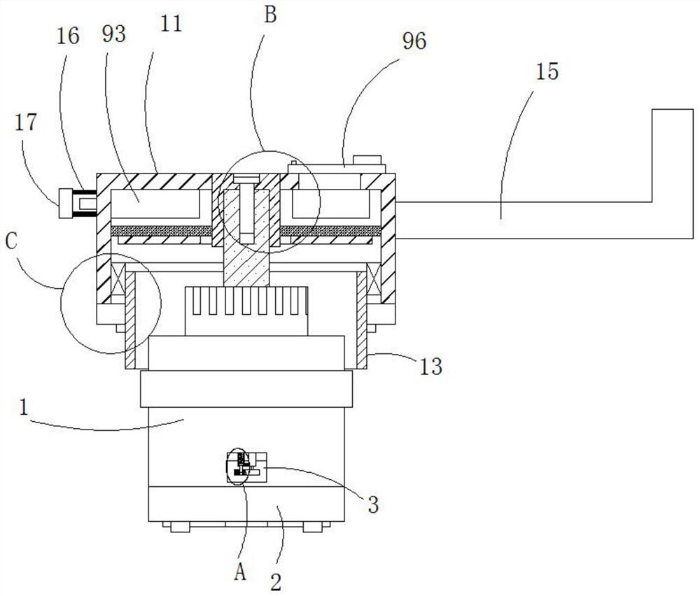
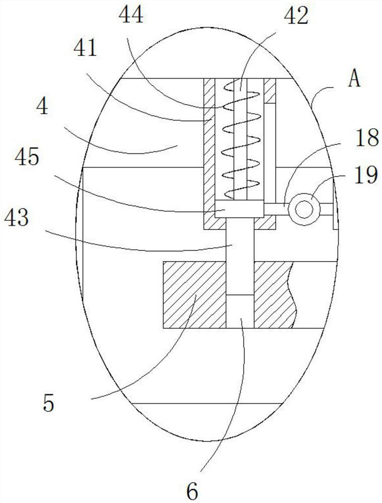
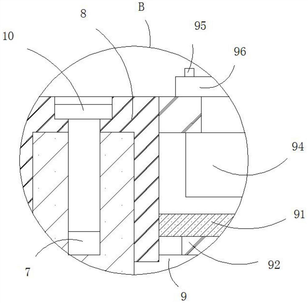
[0024] see Figure 1-4 , a ceramic valve core capable of fast rotation and positioning, comprising a ceramic valve core body 1 and a bottom cover 2, the outer wall of the ceramic valve core body 1 is provided with a rectangular connecting hole 3, and the inner wall of the rectangular connecting hole 3 is fixedly connected with a fixing mechanism 4 , the outer wall of the bottom cover 2 is provided with a rectangular through hole, and the hole wall of the rectangular through hole is movably connected with a plug 5, and the upper surf...


PUM


Abstract

The invention relates to the technical field of valve accessories, and discloses a ceramic valve core capable of realizing quick rotary positioning, which comprises a ceramic valve core body and a bottom cover, a rectangular connecting hole is formed in the outer wall of the ceramic valve core body, a fixing mechanism is connected to the inner wall of the rectangular connecting hole, and a rectangular through hole is formed in the outer wall of the bottom cover; An inserting block is movable connected to the hole wall of the rectangular through hole, and two inserting holes matched with the connecting end of the fixing mechanism are formed in the upper surface of the inserting block. According to the ceramic valve element capable of achieving rapid rotary positioning, the convenience of disassembly and assembly of the ceramic valve element can be effectively improved, meanwhile, the stability of connection of the bottom cover of the ceramic valve element can be guaranteed, the workingreliability of the ceramic valve element can be improved, the protection capacity of the ceramic valve element can be effectively improved, and the ceramic valve element has an anti-freezing function;The using safety and convenience of the ceramic valve element are improved, meanwhile, the service life of the ceramic valve element is guaranteed, and the ceramic valve element can rotate rapidly.

Description

technical field [0001] The invention relates to the technical field of valve fittings, in particular to a ceramic valve core capable of fast rotation and positioning. Background technique [0002] The ceramic spool includes a spool shell installed in the faucet. A rotating core is inserted into the spool shell. The lower end of the rotating core is clamped on the moving valve plate through a shift fork. The moving valve plate and the static valve plate are attached to each other, and the static valve plate It is fixedly installed in the valve core shell, and a pressure piece and a sealing gasket are installed under the static valve plate. The static valve plate has two opposite water inlet through holes, and the moving valve plate has a water inlet hole corresponding to the water inlet through hole. Corresponding to the water outlet through hole, a through hole in the same direction as its central axis is opened on the rotating core. [0003] At present, the bottom cover of...

Claims


Application Information

Patent Timeline
Patent Type & Authority Applications(China)
IPC IPC(8): F16K49/00F16K31/60
CPCF16K49/002F16K31/60
Inventor 殷满强
Owner SHANGHAI GEAR PLASTIC
Learn More