
Rotary quick positioning device

A positioning device and fast technology, applied in positioning devices, precision positioning equipment, clamping, etc., can solve the problems of poor positioning accuracy of parts, inability to achieve high precision, low production efficiency, etc., achieve low manufacturing cost and facilitate large-scale investment Use, high usability effect

Active Publication Date: 2016-07-06
SHANGHAI BOILER WORKS
View PDF9 Cites 0 Cited by
  • Summary
  • Abstract
  • Description
  • Claims
  • Application Information

AI Technical Summary

Problems solved by technology

[0003] The technical problem to be solved by the present invention is to provide a fast rotating positioning device with simple structure, low manufacturing cost, convenient operation, high production efficiency and high processing precision, which solves the need for manual operation when processing a part. The labor force is quite large, and the high-precision requirements cannot be achieved through simple artificial measurement equipment, the positioning accuracy of the parts is poor, the size deviation of the processed parts is large, and the production efficiency of this method is low.

Method used


Image

  • Rotary quick positioning device
  • Rotary quick positioning device
  • Rotary quick positioning device

Examples


Embodiment 1

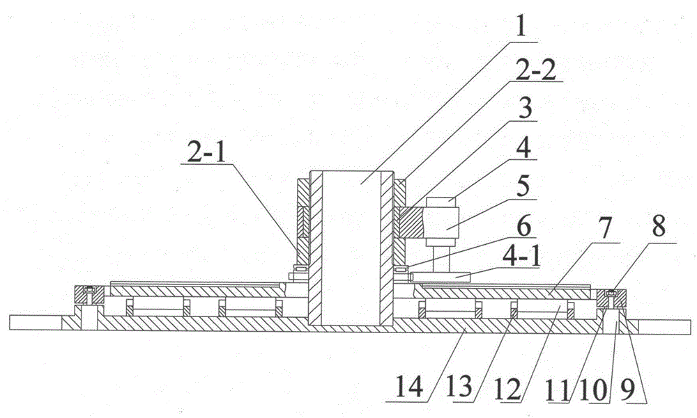
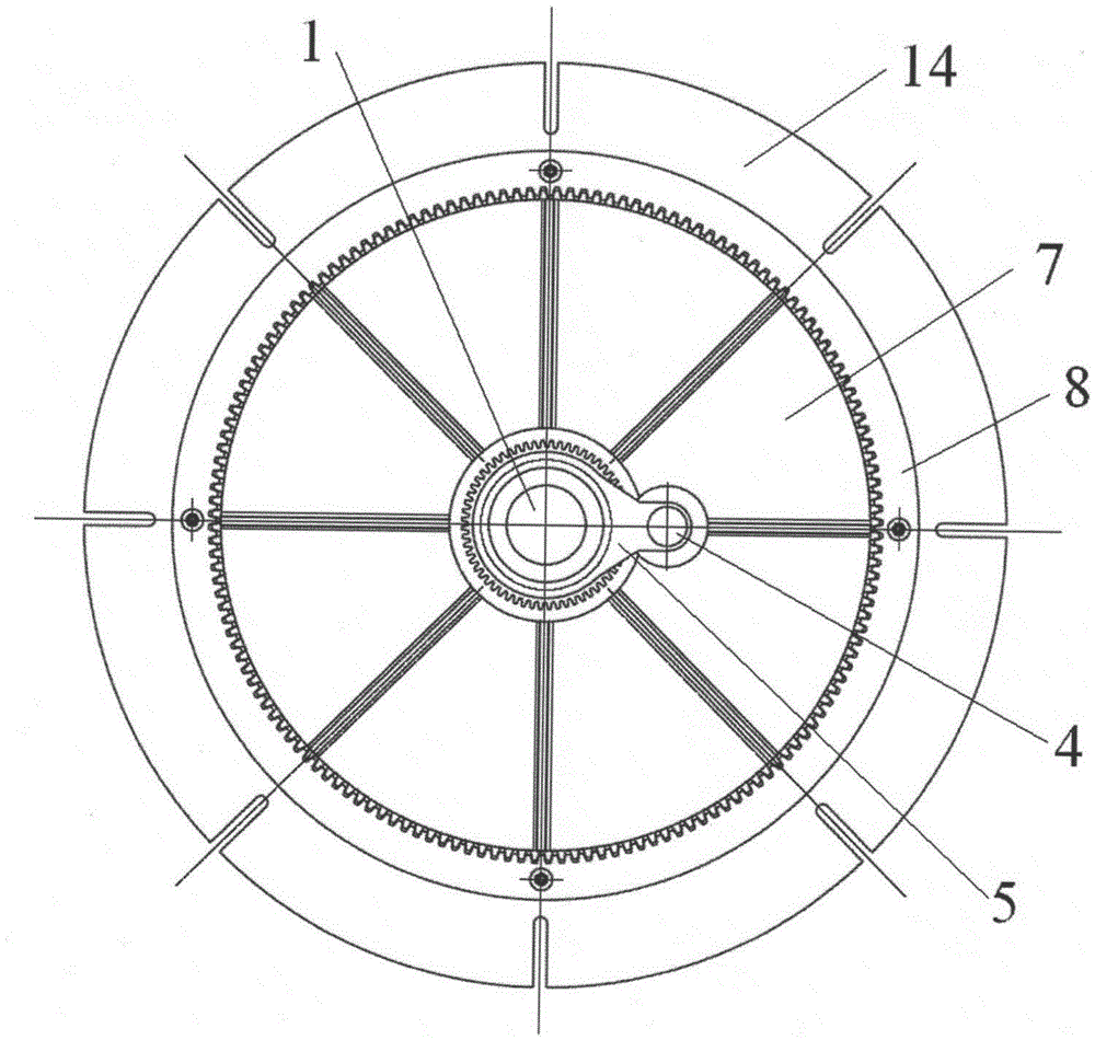
[0025] In the present invention, when the electric transmission mechanism is not installed, the positioning mandrel 1 is installed in the center of the base 14, and the positioning mandrel 1 is covered with a swivel 7, such as Figure 7 , Figure 8 As shown, the small gear ring 7-1 of the swivel 7 passes through the needle bearing 6 (as Figure 5 shown) is connected with the lower pressure ring 2-1, the needle roller bearing 6 is sleeved on the positioning mandrel 1, and the top of the needle roller bearing 6 is fixed with the lower pressure ring 2-1. The large gear ring 7-2 of the swivel 7 is in contact with the needle roller 12, the needle roller 12 is installed on the base 14 through the support block 13, the bottom of the hydraulic jack 10 is installed in the base 14, and the positioning gear ring 9 has a stepped hole. The support rod in the jack 10 is installed in the positioning gear ring 9 step holes, and the two ends are fixed with bottom ring 11 and nut 8 . The top ...

Embodiment 2

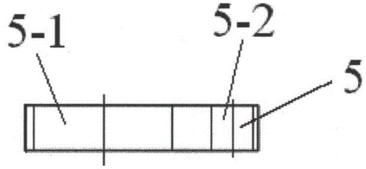
[0034] When the present invention installs the electric transmission mechanism additionally, its structure increases the electric transmission mechanism on the basis of embodiment 1. The lower pressure ring 2-1 is connected with the upper pressure ring 2-2 through an electric transmission mechanism, and the electric transmission mechanism includes clamping blocks 5, such as image 3 , Figure 4 As shown, there is a positioning mandrel 1 in the large hole 5-1 of the clamping block 5, and the clamping block 5 and the positioning mandrel 1 are connected by a lining ring 3, and there is sliding friction contact between them. The top is fixed with the upper pressure ring 2-2. The motor 4 is installed in the small hole 5-2 of the clamping block 5, and the transmission gear 4-1 at the bottom of the motor 4 is meshed with the small gear ring 7-1 of the swivel 7.

[0035] The operation and use steps of a rotating quick positioning device are as follows:

[0036] 1. The parts in the ...


PUM


Abstract

The invention discloses a rotary and rapid positioning device. The rotary and rapid positioning device is characterized by comprising a positioning central spindle, wherein the positioning central spindle is arranged in the center of a base and sleeved with a rotary ring, a small ring gear of the rotary ring is in contact connection with a lower pressing circle through a roller needle bearing, a large ring gear of the rotary ring is in contact connection with a roller needle, the roller needle is connected with a supporting block on the base, a positioning ring gear is arranged on the outer side of the large ring gear of the rotary ring, the positioning ring gear is connected with the base through a hydraulic jack, and the large ring gear is matched with the positioning ring gear. The rotary and rapid positioning device has the advantages of being simple in structure, low in manufacturing cost, convenient to operate, high in production and machining efficiency and the like, and can clamp and position large-scale boring mill and drilling machine parts and rapidly and accurately position workpieces in a rotating mode. The product machining precision is determined by the number of teeth of the rotary ring. Whether an electric transmission mechanism needs to be added or not is judged according to actual use demands. The rotary and rapid positioning device has high practicability and can be brought into use in manufacturing shops on a large scale.

Description

technical field [0001] The invention relates to a fast rotating positioning device, which can be used for clamping and positioning parts of large boring machines and drilling machines. Background technique [0002] At present, for the machining operation of large rotary parts, workshop operators usually manually rotate (clamp) and position the parts on the boring machine platform. When processing a part, manual operation is required, and the labor force is quite large. The requirement of high precision cannot be achieved through simple artificial measuring equipment, the positioning accuracy of the parts is poor, the size deviation of the processed parts is large, and the production efficiency of this method is low. Contents of the invention [0003] The technical problem to be solved by the present invention is to provide a fast rotating positioning device with simple structure, low manufacturing cost, convenient operation, high production efficiency and high processing ...

Claims


Application Information

Patent Timeline
Patent Type & Authority Patents(China)
IPC IPC(8): B23Q3/06B23Q7/00
CPCB23Q3/06B23Q16/06
Inventor 陈力孙厚彬贺少锋顾卫红任艳明
Owner SHANGHAI BOILER WORKS
Learn More