Air source heat pump energy-saving device convenient to install for kitchen

A technology for air source heat pumps and energy-saving devices, which is applied to household refrigeration devices, heat pumps, applications, etc., and can solve the problems of inconvenient installation and disassembly of energy-saving devices, affecting the quality of air-source heat pumps, and long flow time, etc., to achieve simple structure and energy saving Good effect, guaranteed use quality effect

Inactive Publication Date: 2021-01-05
刘文山
View PDF7 Cites 0 Cited by
  • Summary
  • Abstract
  • Description
  • Claims
  • Application Information

AI Technical Summary

Problems solved by technology

[0003] In the prior art, the air source heat pump unit installed in the household kitchen is equipped with an energy-saving device. When the energy-saving device is installed, multiple installation holes are generally opened in the energy-saving device and the air source heat pump, and then the air heat source pump and the air source heat pump are connected by multiple bolts. The energy-saving devices are installed together, the operation is complicated, and it is not convenient to install and disassemble the energy-saving devices; and the cold and hot fluids flow in the pipelines of the energy-saving devices for a long time, and the external fluid easily enters the energy-saving devices through the gap, resulting in cold and hot A large amount of energy is reduced in the process of fluid transportation, which affects the quality of use of the air source heat pump, and the energy saving effect is poor

Method used


Image

  • Air source heat pump energy-saving device convenient to install for kitchen
  • Air source heat pump energy-saving device convenient to install for kitchen
  • Air source heat pump energy-saving device convenient to install for kitchen

Examples


Embodiment Construction

[0017] The following will clearly and completely describe the technical solutions in the embodiments of the present invention with reference to the accompanying drawings in the embodiments of the present invention. Obviously, the described embodiments are only some, not all, embodiments of the present invention. Based on the embodiments of the present invention, all other embodiments obtained by persons of ordinary skill in the art without making creative efforts belong to the protection scope of the present invention.

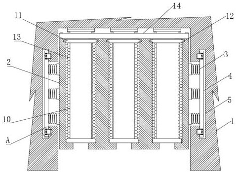
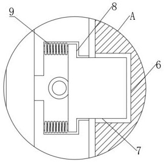
[0018] see Figure 1 to Figure 3 , the present invention provides a technical solution: an air source heat pump energy-saving device that is easy to install in the kitchen, including an air heat source pump body 1, an energy-saving device 2 is clamped inside the air heat source pump body 1, and the surface of the energy-saving device 2 is welded The spring plate 3 is welded with a positioning plate 4 on the surface of the spring plate 3. The inside of the air ...


PUM


Abstract

The invention relates to the related technical field of air heat source pumps, in particular to an air source heat pump energy-saving device convenient to install for a kitchen. The air source heat pump energy-saving device comprises an air heat source pump body, an energy-saving device is clamped inside the air heat source pump body, a spring plate is welded on the surface of the energy-saving device, a heat insulation clamping ring is clamped inside a clamping groove, the interior of the energy-saving device is filled with a heat preservation material, an inner heat exchange pipe is welded to the interior of a sealing plate, and the heat exchange pipe is connected to the surface of the air heat source pump body. The air source heat pump energy-saving device has the beneficial effects that due to the elastic effect of the heat insulation clamping ring, a connecting gap does not generated between the inner heat exchange pipe and the energy-saving device, when the energy-saving device is used, external fluid cannot enter the interior of the energy-saving device, then the fluid energy loss is reduced, and meanwhile, a heat preservation filler is arranged, so that the fluid energy loss is further reduced, the energy-saving effect is good, the use quality of an air heat source pump is guaranteed, and the air source heat pump energy-saving device is suitable for popularization.

Description

technical field [0001] The invention relates to the related technical field of air heat source pumps, in particular to an air source heat pump energy-saving device that is conveniently installed for kitchen use. Background technique [0002] The air source heat pump has multiple advantages such as low cost, easy operation, good heating effect, safety, and cleanliness. Water intake, recharge or soil heat exchange system and special machine room ensure the heating effect and achieve the purpose of energy saving and environmental protection. [0003] In the prior art, the air source heat pump unit installed in the household kitchen is equipped with an energy-saving device. When the energy-saving device is installed, multiple installation holes are generally opened in the energy-saving device and the air source heat pump, and then the air heat source pump and the air source heat pump are connected by multiple bolts. The energy-saving devices are installed together, the operatio...

Claims


Application Information

Patent Timeline
Patent Type & Authority Applications(China)
IPC IPC(8): F25B30/06F25D23/00
CPCF25B30/06F25D23/00
Inventor 刘文山
Owner 刘文山
Why Eureka
Try Eureka