Device and method for comprehensive utilization of wind energy on merchant ships

A technology for wind energy and merchant ships, applied in the field of ships, can solve the problems of small Magnus effect boosting force, large additional wind resistance of ships sailing, and small size of cyclone sails, so as to achieve good thrust effect, reduce ship fuel consumption, and solve wind resistance. larger effect

Active Publication Date: 2022-05-10
QINGDAO UNIV OF SCI & TECH
View PDF10 Cites 0 Cited by
  • Summary
  • Abstract
  • Description
  • Claims
  • Application Information

AI Technical Summary

Problems solved by technology

Although there are many similar patent solutions, there are the following common problems: first, when the ship is sailing against the wind, due to the existence of the rotary sail, it will bring a large additional wind resistance to the ship's navigation and increase the fuel consumption of the ship; Rotor sails need to be installed on the ship deck, so considering the limitations of deck space, ship stability, rotor height and other factors, usually the size of the rotor sail is small, the diameter cannot be too large, and the height cannot be too high. During the process, when the wind comes from the port side or the starboard side, the wind receiving area is smaller, resulting in a smaller Magnus effect along the direction of the ship’s navigation.

Method used


Image

  • Device and method for comprehensive utilization of wind energy on merchant ships
  • Device and method for comprehensive utilization of wind energy on merchant ships
  • Device and method for comprehensive utilization of wind energy on merchant ships

Examples


Embodiment Construction

[0045] In order to make the object, technical solution and advantages of the present invention clearer, the present invention will be further described in detail below in conjunction with the accompanying drawings and embodiments.

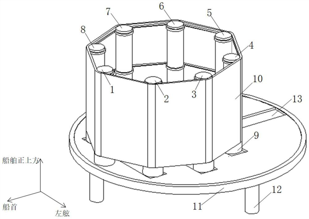
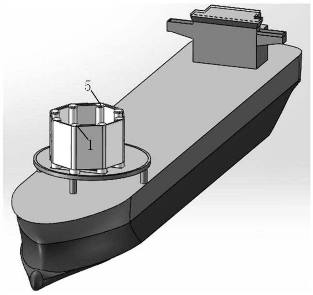
[0046] A device and method for comprehensive utilization of wind energy on merchant ships, such as figure 1 As shown, the device includes: A rotary column 1, B rotary column 2, C rotary column 3, D rotary column 4, E rotary column 5, F rotary column 6, G rotary column 7, H rotary column 8, base 9, Deformed sail 10, platform 11, platform pillar 12, track 13, wherein A spin column 1, B spin column 2, C spin column 3, D spin column 4, E spin column 5, F spin column 6, G spin column 7, The size and shape of the H rotary column 8 are exactly the same, and the three-dimensional model of the present invention on the ship is as figure 2 shown.

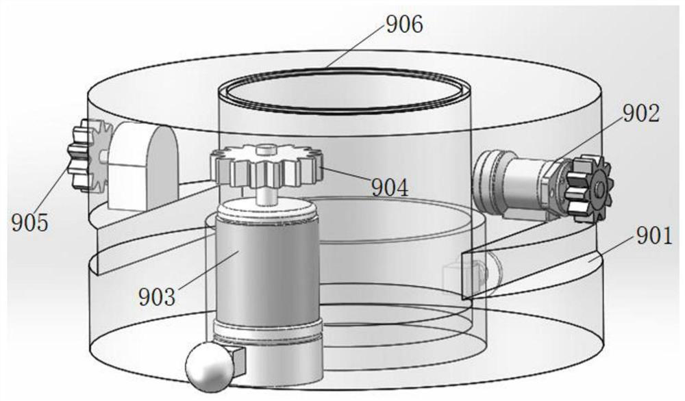
[0047] A base 9 is set at the bottom of the spin column, and the base 9 includes: a base groove 901, a hydrau...


PUM


Abstract

The present invention proposes a device and method for comprehensive utilization of wind energy on merchant ships, the device comprising: A spin column, B spin column, C spin column, D spin column, E spin column, F spin column, G spin column, H Rotary columns, bases, deformed sails, platforms, platform pillars, and rails, the deformed sails of the present invention surround eight rotating columns, thereby forming a rotary sail with a larger size and a nearly circular cross section. Compared with the traditional Magnum As far as the spinner sail is concerned, the deformed sail of the present invention generates a large thrust per unit mass and has a high utilization rate of wind energy. In addition, the deformed sail of the present invention can also be deformed according to different wind directions. When the ship is sailing against the wind, the windward area of ​​the deformed sail can be reduced, which solves the problem of large wind resistance of the traditional rotary sail when sailing against the wind. When the wind blows or the starboard side blows, its diameter is close to 2 / 3 of the ship's width, which can generate a large Magnus thrust, reduce the fuel consumption of the ship, and realize the energy saving and emission reduction of the ship.

Description

technical field [0001] The invention belongs to the technical field of ships, and in particular relates to a device and method for comprehensively utilizing wind energy on merchant ships. Background technique [0002] With the development of trade globalization, the trade of goods among countries in the world has become more and more frequent. The goods transported between countries, especially bulk goods or bulk goods, are mostly transported by ships, but ships not only consume a lot of and the waste gas emitted by burning fuel oil will pollute the environment, so finding new alternative energy sources and energy saving and emission reduction has become an urgent problem to be solved for ships. [0003] In recent years, some researchers and scholars have installed wind energy devices on sailing merchant ships to convert wind energy into the propulsion of ship navigation, reduce the fuel consumption of ships, and realize the energy saving and emission reduction of ships. As...

Claims


Application Information

Patent Timeline
Patent Type & Authority Patents(China)
IPC IPC(8): B63H9/02B63H9/067
CPCB63H9/02B63H9/067Y02T70/5236
Inventor 李博洋郭超邓芳韩淑洁张瑞吕竞泽杨倩倩
Owner QINGDAO UNIV OF SCI & TECH
Why Eureka
Try Eureka