Tie-dyeing equipment
A kind of equipment, the technology of No. 1, applied in the field of tie-dyeing equipment, can solve problems such as low production efficiency, and achieve the effect of speeding up production efficiency
- Summary
- Abstract
- Description
- Claims
- Application Information
AI Technical Summary
Problems solved by technology
Method used
Image

Examples
Embodiment 1
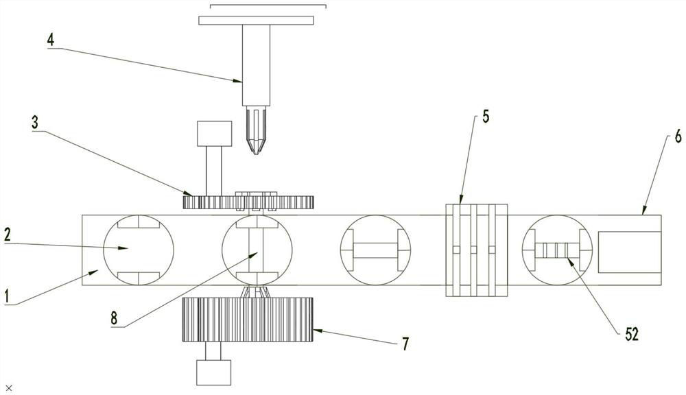
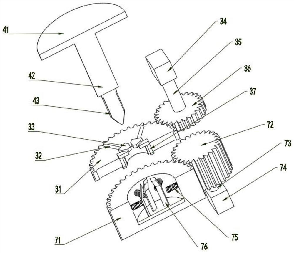
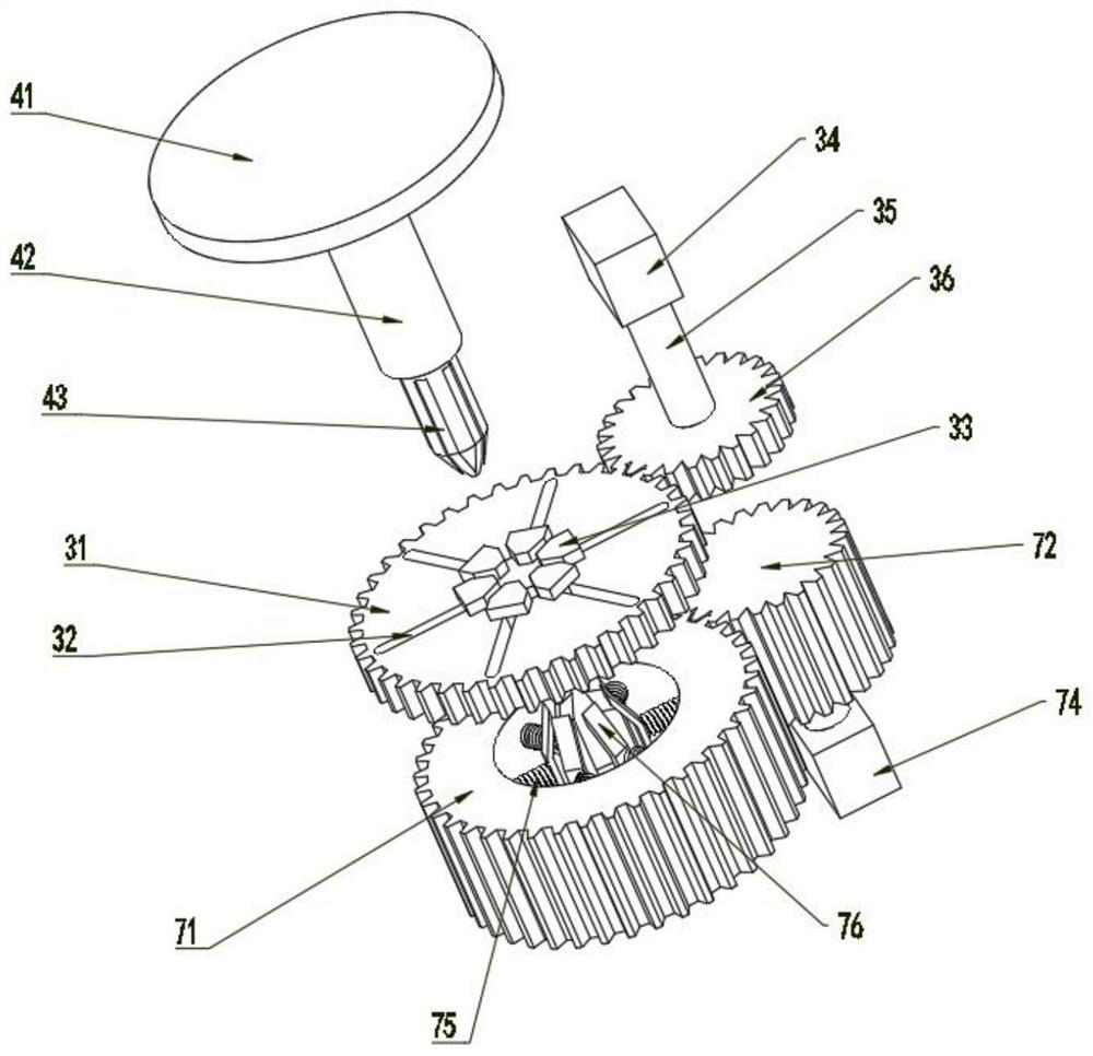
[0023] see Figure 1~3 , in the embodiment of the present invention, a tie-dyeing equipment includes a workbench 1; two sides of the workbench 1 are provided with a twisting device, and the twisting device includes a first twisting mechanism 3 and a second twisting mechanism 7. It is used to twist the cloth 8 into a shape for tie-dyeing; the first twisting mechanism 3 includes a No. 1 driven gear 31, a fixed block 33 and a slide bar 37, and the No. 1 driven gear 31 is along the circumference Direction offers a plurality of chute 32, a plurality of chute 32 slidingly connected with a slide bar 37, one side of the slide bar 37 is provided with a fixed block 33, the No. 1 driven gear 31 is also provided with through hole; the second twisting mechanism 7 includes a No. 2 driven gear 71, a spring 75 and an elastic sheet 76, and a clamping groove is provided in the No. 2 driven gear 71, and multiple The elastic sheets 76 arranged along the circumferential direction, the elastic she...
Embodiment 2
[0027] see figure 1 and Figure 4, in an embodiment of the present invention, the clamping mechanism includes a fixed table 21, a fixed block 22, a fixed groove 23 and a rotating shaft 210, the fixed table 21 is connected to the workbench 1 through the rotating shaft 210, and the fixed block 22 are arranged symmetrically and are slidably connected with the fixed table 21. Between the two fixed blocks 22 is a fixed groove 23, and the fixed groove 23 is a "T"-shaped structure; the intermittent drive mechanism includes a sheave 24, a drive wheel 25. Disc 26, No. 3 connecting rod 27, No. 3 motor 28 and round pin 29. The sheave 24 is sleeved on the periphery of the rotating shaft 210. The sheave 24 is provided with an arc that is slidably connected with the driving wheel 25. The drive wheel 25 is fixed on the disk 26, and a chute connected with the round pin 29 is provided between the two arc-shaped grooves, and the round pin 29 is fixedly installed on the disk 26. The disc 26 is...
Embodiment 3
[0030] see figure 1 and Figure 5 In one embodiment of the present invention, one side of the fixing device 2 is provided with a binding machine 5 that binds the cloth 8 through a binding rope 52. Coordinated moving port 51, the fixed table 21 is provided with the parts used for the processing of the moving port 51; one side of the binding machine 5 is provided with a tie-dyeing mechanism 6, and the tie-dyeing port of the tie-dyeing mechanism 6 is facing Cloth 8 is installed, and described workbench 1 is the workbench surface of movable conveyance.
[0031] Working principle: The fixing device 2 after pre-fixing the cloth 8 and changing the direction of rotation, sends the fixing device 2 to the binding machine 5 through the action of the worktable 1, and the 055 has multiple binding ports and binds the cloth through the binding rope 52 8 is bound, and the cloth 8 after binding is delivered to tie-dyeing mechanism 6 by fixing device 2 and carries out tie-dyeing.
[0032] In...
PUM
 Abstract
Description
Claims
Application Information
 - R&D
- Intellectual Property
- Life Sciences
- Materials
- Tech Scout
- Unparalleled Data Quality
- Higher Quality Content
- 60% Fewer Hallucinations
Browse by: Latest US Patents, China's latest patents, Technical Efficacy Thesaurus, Application Domain, Technology Topic, Popular Technical Reports.
© 2025 PatSnap. All rights reserved.Legal|Privacy policy|Modern Slavery Act Transparency Statement|Sitemap|About US| Contact US: help@patsnap.com