Liquid crystal display device and driving method thereof

A technology of a liquid crystal display device and a liquid crystal layer, which is applied in static indicators, instruments, nonlinear optics, etc., can solve the problems of high brightness in dark states, affecting display effects and anti-peeping effects, and lower contrast, and achieve good anti-peeping effects , Good wide viewing angle display effect

Active Publication Date: 2021-01-08
KUSN INFOVISION OPTOELECTRONICS
View PDF6 Cites 2 Cited by
  • Summary
  • Abstract
  • Description
  • Claims
  • Application Information

AI Technical Summary

Problems solved by technology

[0006] 3. In the narrow viewing angle mode, the display is controlled by the pixel electrode and the common electrode, and by applying a full-surface bias between the common electrode and the viewing angle control electrode, the liquid crystal molecules are tilted to form light leakage at a large viewing angle to achieve the effect of anti-peeping; but narrow In the viewing angle mode, the brightness in the dark state is too high, which leads to a decrease in contrast, whitening on both sides of the panel when viewed from the front, and grayscale inversion at a certain viewing angle, which affects the display effect and anti-peeping effect

Method used


Image

  • Liquid crystal display device and driving method thereof
  • Liquid crystal display device and driving method thereof
  • Liquid crystal display device and driving method thereof

Examples


no. 1 example

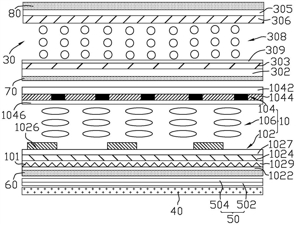
[0041] figure 1 A schematic structural diagram of the liquid crystal display device according to the first embodiment of the present invention is shown. Please refer to figure 1The liquid crystal display device of the first embodiment includes a display panel 10 , a first dimmer 30 and a backlight module 40 , and both the display panel 10 and the first dimmer 30 are disposed on the light emitting side of the backlight module 40 . The display panel 10 includes a second dimmer 101 . In this embodiment, the display panel 10 is disposed between the first dimmer 30 and the backlight module 40 . The first dimmer 30 is used for left and right light collection. Of course, the first dimmer 30 can also be used to receive light up and down. Specifically, the display panel 10 and the first dimmer 30 may be bonded by a frame bonding method, or may be bonded by a full bonding method.

[0042] In this embodiment, a third dimmer 50 is provided on the backlight module 40, the third dimmer...

no. 2 example

[0071] Figure 11 A schematic structural diagram of a liquid crystal display device according to a second embodiment of the present invention is shown. Please refer to Figure 11 , the structure of the liquid crystal display device of this embodiment is similar to the structure of the liquid crystal display device of the first embodiment, the difference is that in this embodiment, the first dimmer 30 is arranged on the display panel 10 and the backlight module 40 between, and the second dimmer 101 is disposed on the first dimmer 30 . The first polarizer 60 is located on the side of the first dimmer 30 away from the display panel 10 , the second polarizer 70 is located between the first dimmer 30 and the display panel 10 , and the third polarizer 80 is located on the side away from the display panel 10 . One side of the first dimmer 30 . Other structures of the liquid crystal display device of this embodiment are similar to those of the first embodiment, and will not be repe...

no. 3 example

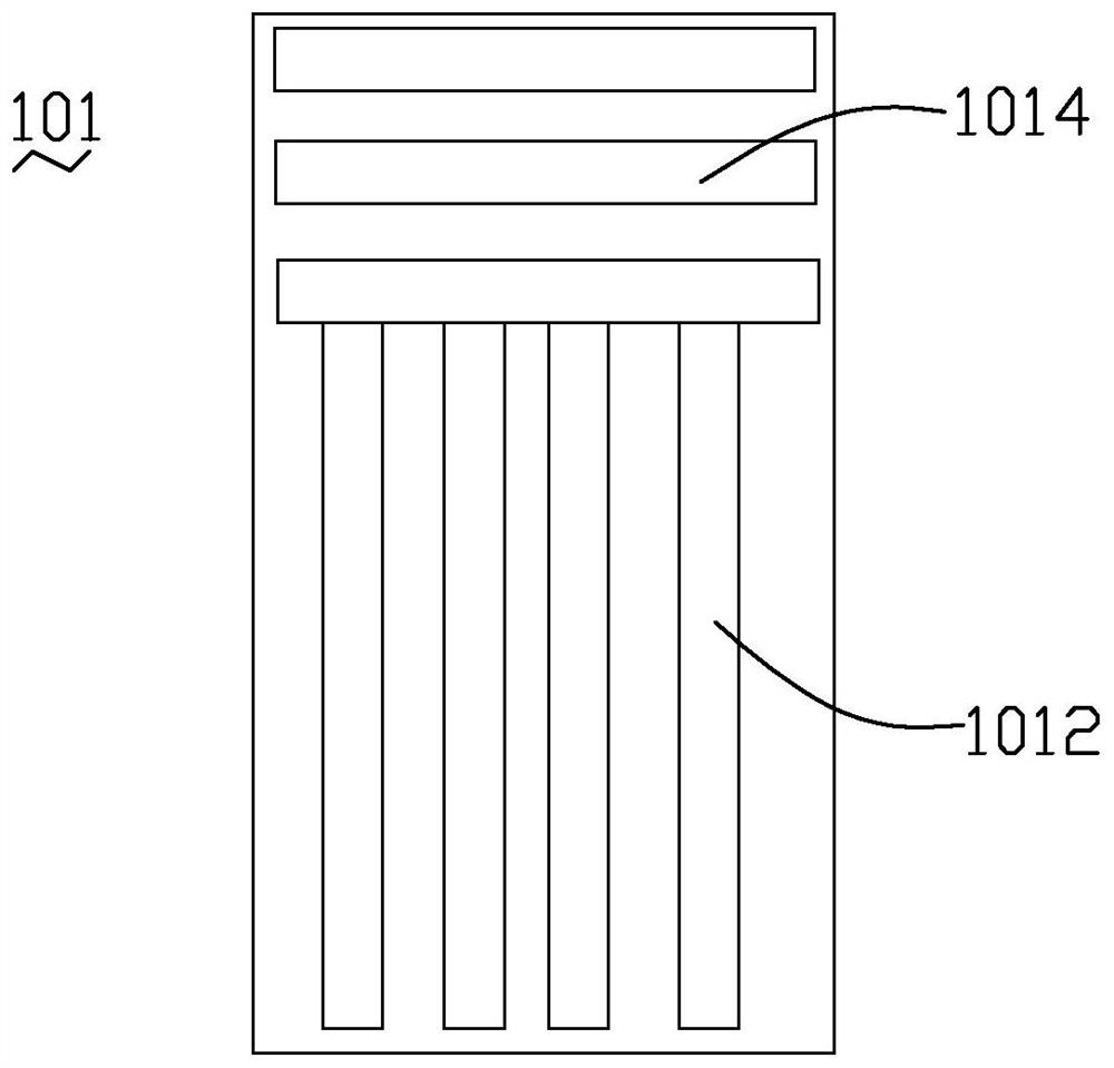
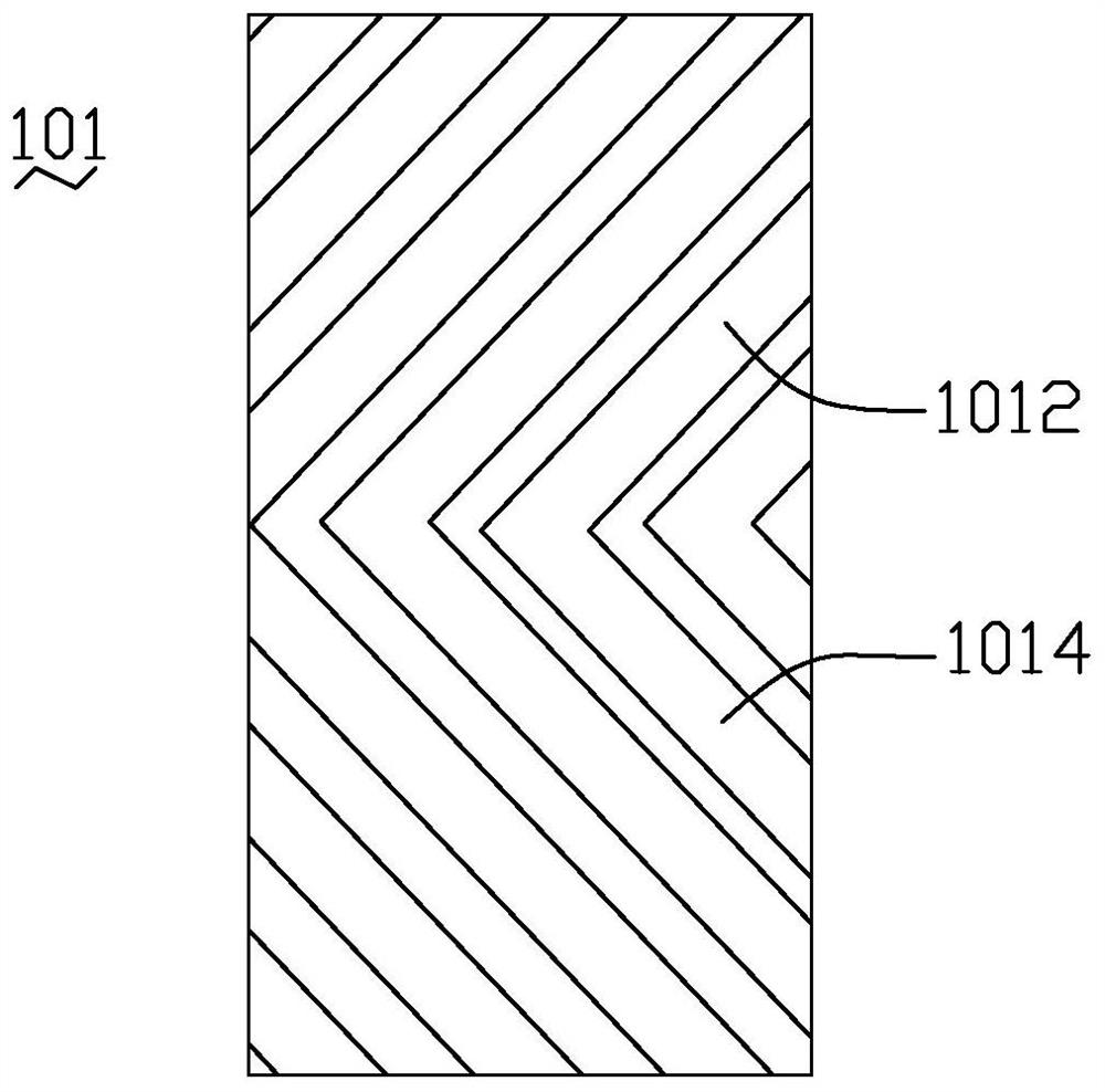
[0074] Figure 12 A schematic structural diagram of a liquid crystal display device according to a third embodiment of the present invention is shown. Please refer to Figure 12 , the structure of the liquid crystal display device of this embodiment is similar to the structure of the liquid crystal display device of the first embodiment, the difference is that, in this embodiment, the third dimmer 50 only includes the second dimming bar (in the figure not shown), the second dimming bar extends along the up and down direction of the liquid crystal display device, realizing left and right bidirectional anti-peeping. In this embodiment, the second dimmer 101 is optional figure 2 , image 3 , Figure 8 and Figure 9 any of them. Other structures of the liquid crystal display device of this embodiment are similar to those of the first embodiment, and will not be repeated here.

[0075] In other embodiments, the third dimmer 50 may also be located on the side of the first di...


PUM


Abstract

The invention relates to a liquid crystal display device and a driving method thereof. The liquid crystal display device comprises a display panel, a first dimmer, a backlight module and a second dimmer. The second dimmer is used for scattering light. The first dimmer comprises a first electrode, a second electrode and a first liquid crystal layer. The backlight module is a light collection type backlight module, and the second dimmer is arranged between the first liquid crystal layer of the first dimmer and the backlight module. Or the liquid crystal display device further comprises a third dimmer, the third dimmer is used for receiving the emergent light of the backlight module, the second dimmer is arranged between the first liquid crystal layer of the first dimmer and the backlight module, and the light receiving direction of the third dimmer corresponds to the light scattering direction of the second dimmer. According to the liquid crystal display device and the driving method thereof, narrow-view-angle display with high contrast can be achieved under narrow-view-angle display, and the peep-proof effect is good; and the second dimmer is matched for light diffusion under wide-viewing-angle display, so that a good wide-viewing-angle display effect can be ensured.

Description

technical field [0001] The invention relates to the field of display technology, in particular to a liquid crystal display device and a driving method thereof. Background technique [0002] With the advancement of social economy and science and technology, users of display devices have different visual requirements for shared information and confidential information, and a display device with a single viewing angle mode can no longer meet the needs of users. Therefore, there is a demand for liquid crystal display panels to switch between wide and narrow viewing angle modes. When the user needs to share information, the wide viewing angle mode is turned on; when the user wants to protect the displayed information, the narrow viewing angle mode is used. [0003] In the prior art, there are the following three methods for switching between wide and narrow viewing angle modes: [0004] 1. Blind technology, the narrow viewing angle is achieved through the external film. When the...

Claims


Application Information

Patent Timeline
Patent Type & Authority Applications(China)
IPC IPC(8): G02F1/13357G02F1/1335G02F1/133G02F1/13G02F1/1347
CPCG02F1/133606G02F1/133528G02F1/13306G02F1/1323G02F1/1347
Inventor 钟德镇廖家德刘显贺沈家军
Owner KUSN INFOVISION OPTOELECTRONICS
Why Eureka
Try Eureka