Liquid crystal display device

A technology of liquid crystal display device and liquid crystal layer, which is applied in the direction of instruments, nonlinear optics, optics, etc., and can solve the problems of high brightness in dark state, affecting display effect and anti-peeping effect, etc.

Active Publication Date: 2020-04-21
KUSN INFOVISION OPTOELECTRONICS
View PDF7 Cites 4 Cited by
  • Summary
  • Abstract
  • Description
  • Claims
  • Application Information

AI Technical Summary

Problems solved by technology

[0006] 3. In the narrow viewing angle mode, the display is controlled by the pixel electrode and the common electrode, and by applying a full-surface bias between the common electrode and the viewing angle control electrode, the liquid crystal molecules are tilted to form light leakage at a large viewing ang

Method used


Image

  • Liquid crystal display device
  • Liquid crystal display device
  • Liquid crystal display device

Examples


no. 1 example

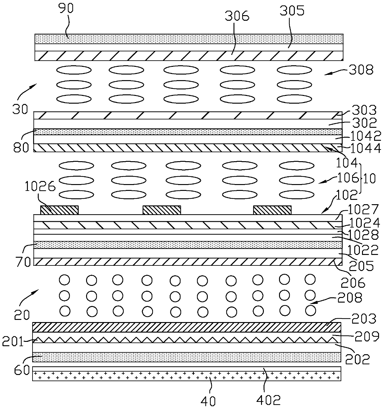
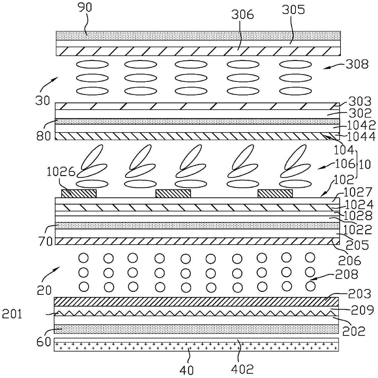
[0044] figure 1 It shows a schematic structural diagram of the liquid crystal display device in the dark state of the first embodiment of the present invention, figure 2 show figure 1 A schematic diagram of the structure of the liquid crystal display device shown in the white state. Please refer to figure 1 and figure 2 , the liquid crystal display device of the first embodiment includes a display panel 10, a first dimmer 20, a second dimmer 30 and a backlight module 40, the display panel 10, the first dimmer 20 and the second dimmer 30 It is arranged on the light emitting side of the backlight module 40 . In this embodiment, the display panel 10 is arranged between the first dimmer 20 and the second dimmer 30, the second dimmer 30 is located on the side of the display panel 10 away from the backlight module 40, the first dimmer 20 is located on a side of the display panel 10 close to the backlight module 40 . The first dimmer 20 includes a prism layer 201 . A light c...

no. 2 example

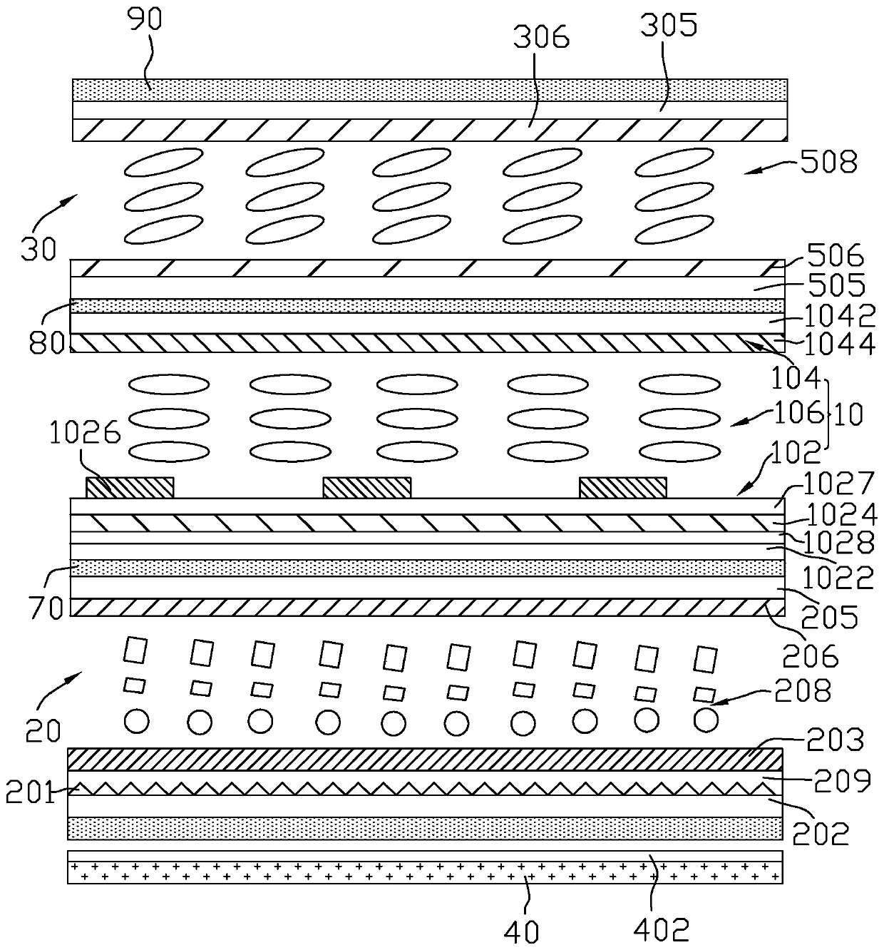
[0061] Figure 5 It is a schematic structural diagram of a liquid crystal display device according to the second embodiment of the present invention. like Figure 5 As shown, the structure of the liquid crystal display device of this embodiment is basically the same as that of the first embodiment, the difference is that in this embodiment, both the first dimmer 20 and the second dimmer 30 are set On the side of the display panel 10 away from the backlight module 40, the second dimmer 30 is arranged between the first dimmer 20 and the display panel 10, the prism layer 201 is arranged on the display panel 10, and the first polarizer 60 The second polarizer 70 is arranged between the display panel 10 and the second dimmer 30, and the third polarizer 80 is arranged between the first dimmer 20 and the second dimmer 30. Between the dimmers 30 , the fourth polarizer 90 is disposed on a side of the first dimmer 20 away from the backlight module 40 . Moreover, the prism layer 201 a...

no. 3 example

[0065] Image 6 It is a schematic structural diagram of a liquid crystal display device according to a third embodiment of the present invention. like Image 6 As shown, the structure of the liquid crystal display device of this embodiment is basically the same as that of the liquid crystal display device of the second embodiment, the difference is that in this embodiment, the first dimmer 20 is arranged between the second dimmer 30 and Between the display panels 10, the first polarizer 60 is arranged on the side of the display panel 10 close to the backlight module 40, the second polarizer 70 is arranged between the display panel 10 and the first dimmer 20, and the third polarizer 80 It is disposed between the first dimmer 20 and the second dimmer 30 , and the fourth polarizer 90 is disposed on a side of the second dimmer 30 away from the backlight module 40 .

[0066] The transmission axis directions of the polarizers on both sides of the display panel 10 are perpendicular...


PUM


Abstract

The invention provides a liquid crystal display device which comprises a display panel, a light modulator used for light receiving and a backlight module. A prism layer is arranged on the display panel and/or the light modulator, a light collecting film is arranged on the backlight module and used for narrowing emergent light from the backlight module leftwards and rightwards, and the prism layeris used for diffusing the light leftwards and rightwards. The light modulator comprises a first light modulator, the first light modulator comprises a first electrode, a second electrode and a first liquid crystal layer, the first liquid crystal layer is located on one side, away from the backlight module, of the prism layer, and at least one light modulator is arranged on the side, away from thebacklight module, of the display panel. According to the liquid crystal display device, a narrow viewing angle mode can be achieved, a contrast ratio is high, and a peep-proof effect is good; peep prevention can be realized by receiving light at a large viewing angle, front-view brightness is not influenced, and a penetration rate is relatively high; color cast can be effectively improved; and twosides can be prevented from being whitened in front view, visual performance under a narrow view angle is improved, and a good wide-narrow view angle display effect can be obtained.

Description

technical field [0001] The invention relates to the field of display technology, in particular to a liquid crystal display device. Background technique [0002] With the advancement of social economy and science and technology, users of display devices have different visual requirements for shared information and confidential information, and a display device with a single viewing angle mode can no longer meet the needs of users. Therefore, there is a demand for liquid crystal display panels to switch between wide and narrow viewing angle modes. When the user needs to share information, the wide viewing angle mode is turned on; when the user wants to protect the displayed information, the narrow viewing angle mode is used. [0003] In the prior art, there are the following three methods for switching between wide and narrow viewing angle modes: [0004] 1. Blind technology, the narrow viewing angle is achieved through the external film. When the wide viewing angle mode is r...

Claims


Application Information

Patent Timeline
IPC IPC(8): G02F1/1347G02F1/1335G02F1/13357G02F1/1337
CPCG02F1/1347G02F1/1335G02F1/133606G02F1/1337G02F1/133528
Inventor 钟德镇刘显贺
Owner KUSN INFOVISION OPTOELECTRONICS
Why Eureka
Try Eureka