
Medical disinfection device capable of automatically avoiding obstacles and increasing spraying speed

A technology for a disinfection device and obstacles, applied in the field of medical care, can solve the problems of obstructing public traffic, difficult to atomize the disinfectant, hidden dangers, etc., and achieves the effect of avoiding touching obstacles, solving incomplete disinfection, and eliminating potential safety hazards.

Inactive Publication Date: 2021-01-12
杭州医迈医疗器械有限公司
View PDF0 Cites 1 Cited by
  • Summary
  • Abstract
  • Description
  • Claims
  • Application Information

AI Technical Summary

Problems solved by technology

[0002] At present, hospital disinfection equipment usually requires staff to manually change directions for disinfection, which often misses the disinfection of lower air and ground parts. Sometimes, when some obstacles appear during the disinfection process, the staff or part of the disinfection equipment cannot be very sensitive. The situation of avoiding and adjusting the spraying amount will hinder public traffic; and most of the ultraviolet disinfection equipment used in some hospitals is only used in wards, and is not suitable for disinfection in public areas; and some disinfectants are not easy to atomize after disinfection, and will The ground is wet and slippery, and there are certain safety hazards

Method used


Image

  • Medical disinfection device capable of automatically avoiding obstacles and increasing spraying speed
  • Medical disinfection device capable of automatically avoiding obstacles and increasing spraying speed
  • Medical disinfection device capable of automatically avoiding obstacles and increasing spraying speed

Examples


Embodiment Construction

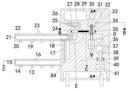
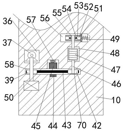
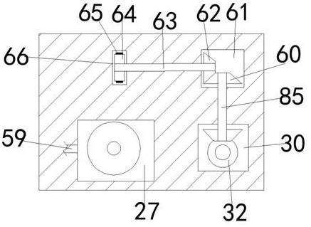
[0020] Combine below Figure 1-6 The present invention is described in detail, wherein, for the convenience of description, the orientations mentioned below are defined as follows: figure 1 The up, down, left, right, front and back directions of the projection relationship itself are the same.

[0021]A medical disinfection device that can automatically avoid obstacles and spraying speeds described in conjunction with accompanying drawings 1-6 includes a main body box 10, and a wire wheel power chamber 58 is arranged inside the main body box 10, and a wire wheel power chamber 58 is provided on the wire wheel power chamber 58. The side is provided with a speed regulating power chamber 36, and the upper left side of the speed regulating power chamber 36 is provided with a large bevel gear 78, and the left side of the large bevel gear 78 is connected with a speed regulating gear chamber 77, and the speed regulating gear The lower side of the chamber 77 is communicated with a fan...


PUM


Abstract

The invention relates to the related field of medical nursing, and discloses a medical disinfection device capable of automatically avoiding obstacles and increasing the spraying speed. The medical disinfection device comprises a main body box, wherein a wire wheel power cavity is formed in the main body box, a speed regulating power cavity is formed in the upper side of the wire wheel power cavity, a large bevel gear is arranged above the left side of the speed regulating power cavity, a speed regulated gear cavity is formed in the left side of the large bevel gear in a communicating manner,a fan blade power cavity is formed in the lower side of the speed regulated gear cavity in a communicating manner, and a fan blade power cavity is formed in the upper side of the speed regulated gearcavity. The device can disinfect the air and the ground at the low position of a hospital, so that the problem that the disinfection at the low position of the hospital is not thorough is solved; meanwhile, the blowing work for the disinfected wet ground can be completed while the disinfection is carried out, so that the phenomenon that the ground is too wet due to the small size, and then the passing people slide can be avoided, the potential safety hazards are completely eradicated, meanwhile, the circulation of the air in a disinfection bowl can be enhanced; and the device is also providedwith an induction switch, so that the spraying equipment can be automatically lowered and adjusted, and the touch with the obstacles is avoided.

Description

technical field [0001] The invention relates to the related field of medical care, in particular to a medical disinfection device that can automatically avoid obstacles and spraying speed. Background technique [0002] At present, hospital disinfection equipment usually requires staff to manually change directions for disinfection, which often misses the disinfection of lower air and ground parts. Sometimes, when some obstacles appear during the disinfection process, the staff or part of the disinfection equipment cannot be very sensitive. The situation of avoiding and adjusting the spraying amount will hinder public traffic; and most of the ultraviolet disinfection equipment used in some hospitals is only used in wards, and is not suitable for disinfection in public areas; and some disinfectants are not easy to atomize after disinfection, and will The ground is wet and slippery, and there are certain safety hazards. Contents of the invention [0003] The object of the pr...

Claims


Application Information

Patent Timeline
Patent Type & Authority Applications(China)
IPC IPC(8): A61L2/22A61L2/24A61L2/26A61L9/14
CPCA61L2/22A61L2/24A61L2/26A61L9/14A61L2202/16
Inventor 何邓梅
Owner 杭州医迈医疗器械有限公司
Learn More