
Prefabricated beam anti-tilting support

A prefabricated beam and anti-tilt technology, which is applied in the direction of bridges, bridge construction, erection/assembly of bridges, etc., can solve the problems of poor stability and length of prefabricated beams, achieve good stability, ensure stability, and simplify the structure

Pending Publication Date: 2021-01-12
ROAD & BRIDGE SOUTH CHINA EINGINEERING CO LTD +1
View PDF0 Cites 0 Cited by
  • Summary
  • Abstract
  • Description
  • Claims
  • Application Information

AI Technical Summary

Problems solved by technology

[0004] In order to overcome the above technical problems, especially the problem of long prefabricated beams and poor stability during movement, the following technical solutions are proposed:

Method used


Image

  • Prefabricated beam anti-tilting support
  • Prefabricated beam anti-tilting support
  • Prefabricated beam anti-tilting support

Examples


Embodiment 1

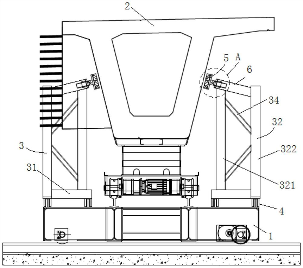
[0035] In one embodiment provided by this application, such as figure 1 As shown, the uprights 32 include a first upright 321 close to the prefabricated beam 2 and a second upright 322 far away from the prefabricated beam 2 , and two second braces 34 are arranged between the first upright 321 and the second upright 322 . Optionally, the two second diagonal braces 34 are in a figure-eight shape, the ends of the two second diagonal braces 34 arranged on the first column 321 are far apart, and the ends of the two second diagonal braces 34 arranged on the second column 322 are relatively far apart. close. The splayed bracing makes the first column 321 and the second column 322 have a containment and support structure, so that the first column 321 and the second column 322 can support each other.

Embodiment 2

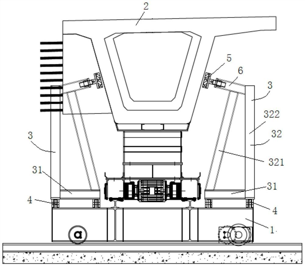
[0037] In one embodiment provided by this application, such as figure 2 As shown, the column 32 includes a first column 321 close to the prefabricated beam 2 and a second column 322 away from the prefabricated beam. The top of the first column 321 is inclined to the second column, and the second column 322 is perpendicular to the beam. The first column 321 is arranged obliquely so that the first column 321 can support the first brace 6 eccentrically. When the support frame 3 supports the prefabricated beam 2 and is subjected to the pressure exerted by the prefabricated beam 2 on the support frame, the beam 31 is bolted on the basis of the connecting seat , the first column can restrain the first brace 6 from exerting too much force on the second column 322, thereby ensuring the stability of the entire support frame structure.

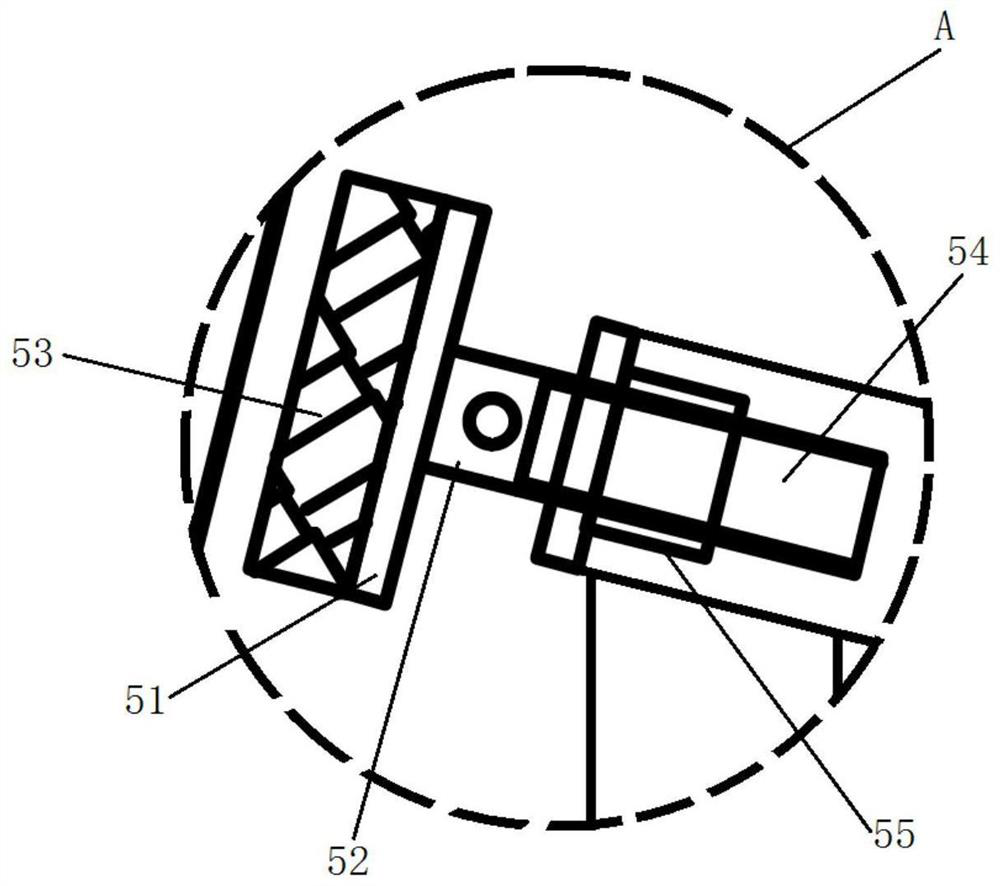
[0038] In the examples provided by this application, such as image 3 As shown, the tightening mechanism 5 includes a tightening plate 51 that tighte...


PUM


Abstract

The invention relates to a prefabricated beam anti-toppling support which comprises a movable platform, turnover supporting frames arranged on the lengthwise side edge of the movable platform in pairsand connecting bases connected with the supporting frames and the movable platform, wherein one end of each supporting frame is connected with a connecting base, and the other end of each supportingframe is connected with a screw type jacking device used for abutting against a prefabricated beam web. The supporting frames are arranged on the lengthwise side edges of the movable platform in pairs, namely, the supporting frames are arranged on the two sides of the prefabricated beam, the web of the prefabricated beam is jacked through the jacking device, the supporting frames are stably fixedto the movable platform through the connecting bases, and therefore it is guaranteed that the prefabricated beam has good stability in the moving process. The anti-toppling support of the frame structure is formed on the basis of cross beams, stand columns and jacking devices, so that the whole anti-toppling support is simple in structure and convenient to manufacture and install.

Description

technical field [0001] The invention relates to the technical field of construction, in particular to a prefabricated beam anti-tilt bracket. Background technique [0002] In the process of bridge building construction, in order to improve the construction efficiency of the bridge, the construction of the bridge beam section will be carried out at the same time during the bridge foundation construction process, so as to improve the construction efficiency of the bridge and shorten the construction period of the bridge. Among them, the prefabricated box girder can meet the conditions of synchronous construction with the bridge substructure, thereby shortening the construction period of the bridge, can be produced in a factory, and the quality of the prefabricated box girder is easier to control than the cast-in-place box girder. It has been more and more popular in bridge construction. The wider the application. [0003] At present, prefabricated box girders are mainly compl...

Claims


Application Information

Patent Timeline
IPC IPC(8): E01D21/00
CPCE01D21/00
Inventor 徐建雄董辉刘全峰林彬陈玉良聂启波商小平朱君伟兰冰黄健柏
Owner ROAD & BRIDGE SOUTH CHINA EINGINEERING CO LTD
Learn More