Rotary compressor and method

A technology of rotary compressor and pressure control chamber, which is applied in the direction of rotary piston machinery, rotary piston pump, rotary piston type/swing piston type pump components, etc., which can solve the problems of changing and unable to realize the capacity of air conditioner compressors, etc.

Active Publication Date: 2021-01-12
SHANGHAI HITACHI ELECTRICAL APPLIANCES CO LTD
View PDF3 Cites 0 Cited by
  • Summary
  • Abstract
  • Description
  • Claims
  • Application Information

AI Technical Summary

Problems solved by technology

have figure 1 The compressor of the cylinder shown in cannot realize the air conditioner compressor capacity (volume flow) can vary according to the load

Method used


Image

  • Rotary compressor and method
  • Rotary compressor and method
  • Rotary compressor and method

Examples


Embodiment 1

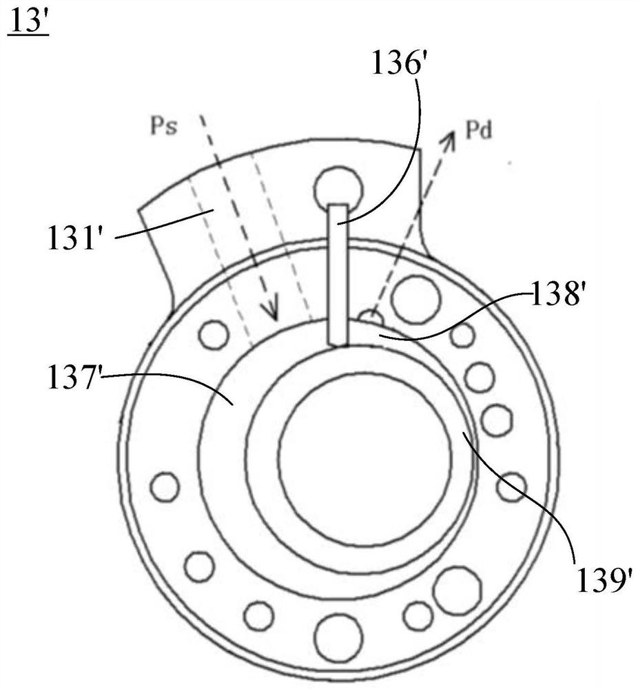
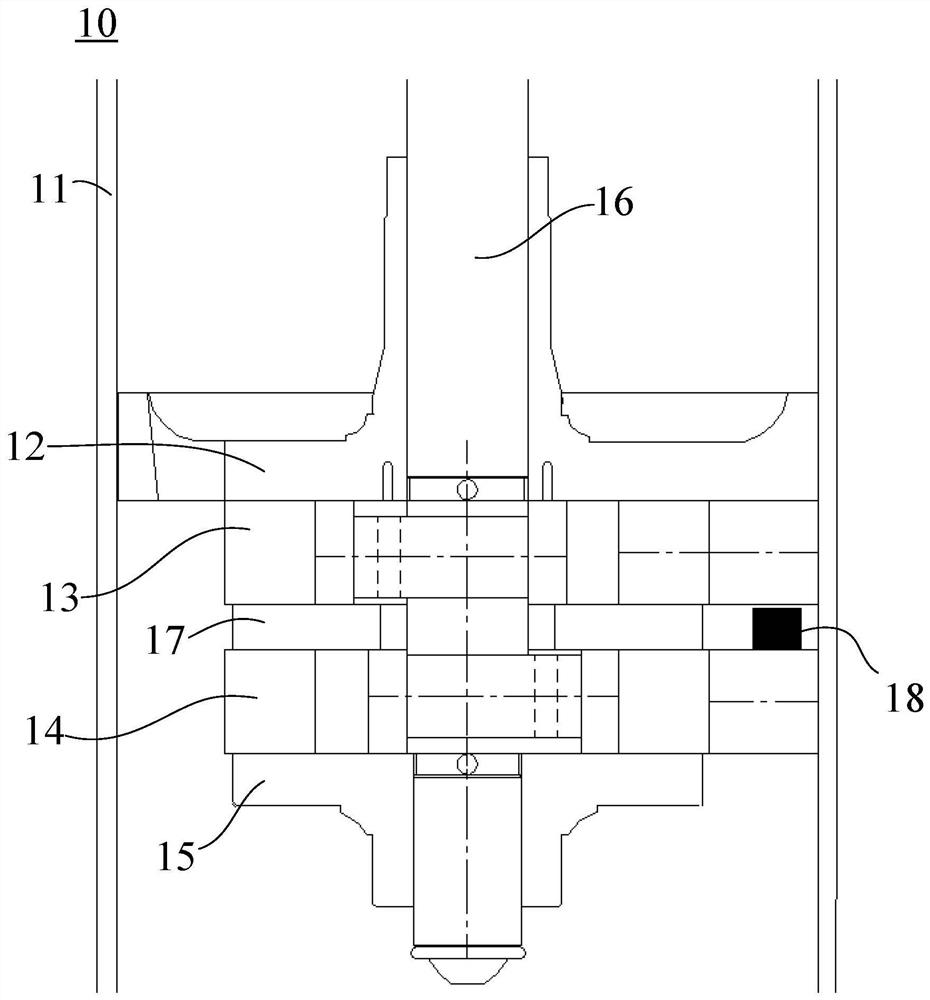
[0073] figure 2 It is a structural schematic diagram of a rotary compressor 10 . figure 2 The compressor 10 shown in the figure includes a casing 11, and two cylinders are arranged in the casing 11, that is, a first cylinder 13 and a second cylinder 14, the first suction cylinder is an upper cylinder, and the second cylinder 14 is a lower cylinder, some In an embodiment, the first cylinder 13 may be a lower cylinder, and the second cylinder 14 may be an upper cylinder. The first cylinder 13 and the second cylinder 14 are separated by an intermediate plate 17 . The first cylinder 13 is provided with a first rotary piston 139 , and the second cylinder 14 is provided with a second rotary piston. The two ends of the first cylinder 13 are the upper cylinder head 12 and the middle plate 17, and the two ends of the second cylinder 14 are the middle plate 17 and the lower cylinder head 15 respectively. The housing 11 is provided with a crankshaft 16. The crankshaft 16 has a long ...

Embodiment 2

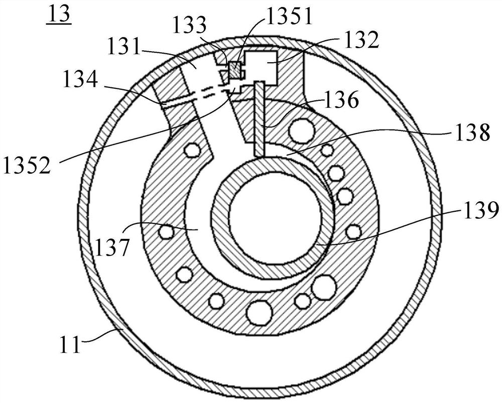
[0079] Figure 5 It is a schematic structural diagram of the first cylinder 13 in Embodiment 2. Figure 6 yes Figure 5 Schematic diagram of the structure of the slider 1351 in the second position. refer to Figure 5 and Figure 6 , the difference between this embodiment and Embodiment 1 is that there is a connecting air channel 1353 inside the slider 1351, when the slider 1351 is in the first position, the second control air channel 134 is connected to the control chamber through the connecting air channel 1353 132 conducts, and when the slider 1351 is in the second position, the first control air channel 133 communicates with the control chamber 132 through the connecting air channel 1353 . The first position of the slider 1351 is the lower end of the chute 1352 , and the second position of the slider 1351 is the upper end of the chute 1352 .

[0080] Figure 5 The slider 1351 shown in is in the first position. At this time, the slider 1351 blocks the first control air...

Embodiment 3

[0083] Figure 7 It is a schematic structural diagram of the first cylinder 13 in Embodiment 3. refer to Figure 7 The difference between this embodiment and Embodiment 2 is that: one side of the slot of the first vane 136 is provided with a stop groove 1354, and when the slider 1351 is in the second position, the stop groove 1354 and the inside of the casing 11 The space communicates to lock the first blade 136 . When the slider 1351 is at the first position, the stop groove 1354 communicates with the first suction channel 131 . When the slider 1351 slides to the second position (the upper end of the sliding slot 1352), the stop groove 1354 is filled with high-pressure gas, and the high-pressure gas presses the first vane 136, so that the first vane 136 is fixed on the first vane 136 in the slot.

[0084] In some embodiments, one side of the first vane 136 is provided with a pneumatic locking cylinder. When the slider 1351 is in the second position, the free end of the pn...


PUM


Abstract

The invention discloses a rotary compressor and a method. The rotary compressor comprises a shell, a first cylinder, a second cylinder, a first blade and a second blade, wherein the first cylinder isprovided with a pressure control cavity, wherein the second end of a first blade groove is communicated with the pressure control cavity; the pressure control cavity is connected to a first air suction channel through a first control air passage; the pressure control cavity is connected to the inner space of the shell through a second control air passage; and only one of the first control air passage and the second control air passage is in a connected state at the same moment. According to the rotary compressor and the method, the pressure control cavity is arranged in the cylinder, the bladegroove of the cylinder is communicated with the pressure control cavity, and the pressure control cavity is respectively communicated with low-pressure gas and high-pressure gas through two differentcontrol air passages, so that the cylinder stops compressing a refrigerant when the low-pressure gas is introduced into the pressure control cavity, the cylinder normally compresses the refrigerant when the low-pressure gas is introduced into the pressure control cavity, the switching of the capacity of the compressor is achieved, and the requirements for different loads in different seasons aremet.

Description

technical field [0001] The present invention relates to a technology in the field of air-conditioning and refrigeration, and more specifically, relates to a rotary compressor and a method thereof. Background technique [0002] In today's society, air conditioners are used more and more frequently. In order to improve the quality of life, air conditioners will also be turned on in transitional seasons (spring and autumn). And when I get home in winter, I hope that the air conditioner can blow out hot air and be able to operate at a super load. The air conditioner can take into account the rapid heating in winter and the extremely small load operation in the transitional season, which requires the compressor to be able to take care of both, that is, the capacity (volume flow) of the air conditioner compressor can be changed according to the load. figure 1 It is a schematic diagram of an existing cylinder structure. figure 1 The inner chamber of the cylinder 13 shown in the f...

Claims


Application Information

Patent Timeline
Patent Type & Authority Applications(China)
IPC IPC(8): F04C18/356F04C23/00F04C28/24F04C29/12
CPCF04C18/3562F04C29/12F04C28/24F04C23/001
Inventor 潘瑾王艳珍刘春慧
Owner SHANGHAI HITACHI ELECTRICAL APPLIANCES CO LTD
Why Eureka
Try Eureka