Intelligent building balance detection system and method based on infrared temperature measurement
A technology for intelligent building and balance detection, applied in radiation pyrometry, measuring devices, surveying and navigation, etc., can solve the problems of construction site restrictions, expensive settlement detection devices, and difficult to determine detection points, and solve difficult observation. Effect
- Summary
- Abstract
- Description
- Claims
- Application Information
AI Technical Summary
Problems solved by technology
Method used
Image

Examples
Embodiment 1
[0029] The traditional method of building balance detection is mainly to carry out balance detection during the construction stage. Due to the serious restrictions on the construction site, it is difficult to implement the calibration method of orthogonal and vertical theodolite. The point is difficult to determine the problem. At the same time, because these observation methods need to be implemented at observation points higher than buildings, and the buildings in our country are getting taller and taller, it is difficult to implement them during the construction stage, and no inspection will be carried out after completion. The invention judges the balance of the building by detecting the temperature of the surrounding environment. When the temperature of the surrounding environment is consistent, the building is in a balanced state. When there is a temperature difference in the surrounding environment, it means that the building has settled. Especially in mountainous areas...
Embodiment 2
[0047] The observation of high-rise buildings is balanced, and infrared receivers are only installed on one floor. The detection results are not accurate enough, and infrared receivers need to be installed on every floor of the building.
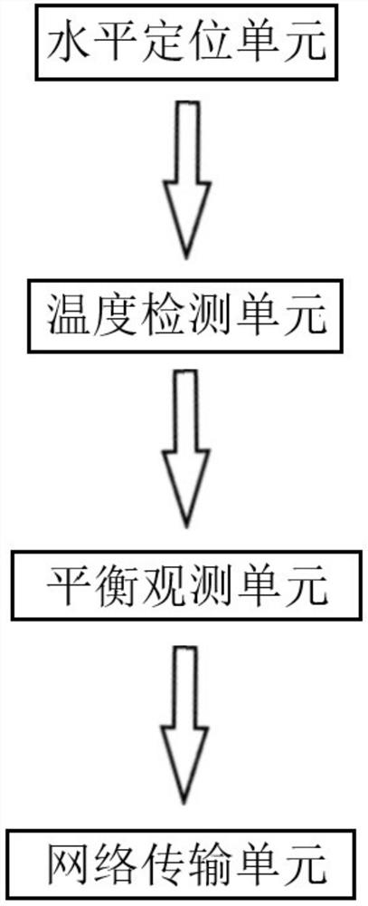
[0048] In this example, if figure 1 As shown, an intelligent building balance detection system based on infrared temperature measurement, including a horizontal positioning unit, a temperature detection unit, a balance observation unit and a signal transmission unit;
[0049] The horizontal positioning unit determines that the infrared receiver of the temperature detection unit is at the same horizontal position;
[0050] A temperature detection unit, including a plurality of infrared receivers, is arranged around the outer wall of the building at the same level to detect the temperature of the surrounding environment;
[0051] The balance observation unit judges the current building balance state by judging whether there is a temperature d...
Embodiment 3
[0065] The settlement of the foundation of the building may settle smoothly, that is, the overall settlement of the building does not appear in a tilted state. At this time, the existing balance detection method cannot detect the settlement of the building. The present invention can judge according to the recorded data in the cloud.
[0066] In this example, if figure 1 As shown, an intelligent building balance detection system based on infrared temperature measurement, including a horizontal positioning unit, a temperature detection unit, a balance observation unit and a signal transmission unit;
[0067] The horizontal positioning unit determines that the infrared receiver of the temperature detection unit is at the same horizontal position;
[0068] A temperature detection unit, including a plurality of infrared receivers, is arranged around the outer wall of the building at the same level to detect the temperature of the surrounding environment;
[0069] The balance obser...
PUM
 Abstract
Description
Claims
Application Information
 - R&D
- Intellectual Property
- Life Sciences
- Materials
- Tech Scout
- Unparalleled Data Quality
- Higher Quality Content
- 60% Fewer Hallucinations
Browse by: Latest US Patents, China's latest patents, Technical Efficacy Thesaurus, Application Domain, Technology Topic, Popular Technical Reports.
© 2025 PatSnap. All rights reserved.Legal|Privacy policy|Modern Slavery Act Transparency Statement|Sitemap|About US| Contact US: help@patsnap.com