
A micro-thrust measuring device

A measuring device and micro-thrust technology, applied in measuring devices, force/torque/power measuring instruments, instruments, etc., can solve the problems of low measurement accuracy, achieve accurate measurement, eliminate the influence of friction and gravity, and improve sensitivity Effect

Active Publication Date: 2021-10-22
UNIV OF ELECTRONICS SCI & TECH OF CHINA
View PDF8 Cites 0 Cited by
  • Summary
  • Abstract
  • Description
  • Claims
  • Application Information

AI Technical Summary

Problems solved by technology

[0006] The purpose of the present invention is to provide a micro-thrust measuring device to solve the existing problem of low measurement accuracy

Method used


Image

  • A micro-thrust measuring device
  • A micro-thrust measuring device
  • A micro-thrust measuring device

Examples


Embodiment 1

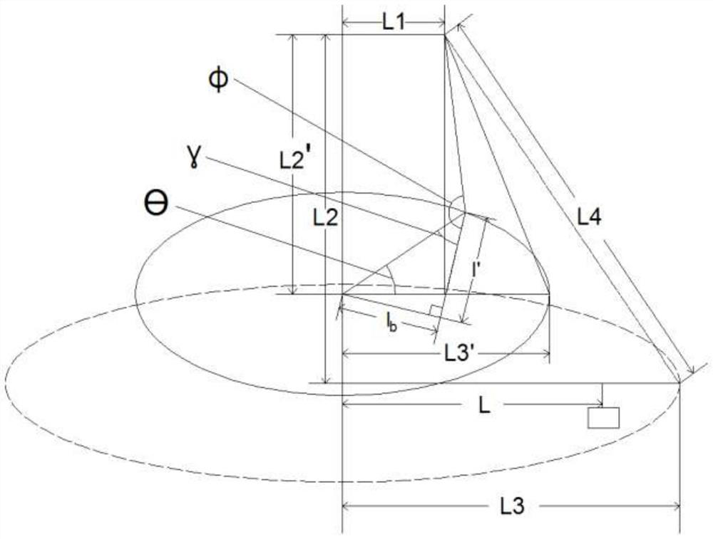
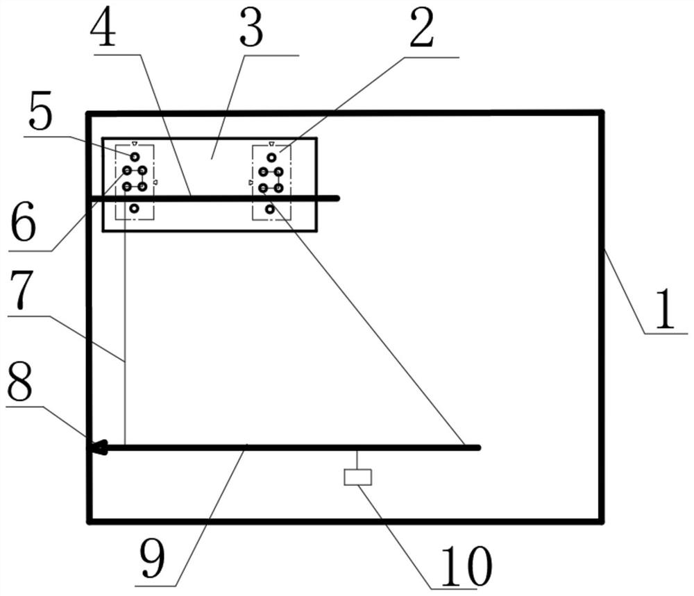
[0044] Such as Figure 1-2 As shown, a kind of micro-thrust measuring device comprises support 1, and the upper side of described support 1 is provided with fixed frame 3, and described fixed frame 3 is equipped with two left and right symmetrical XY displacement platforms 2, and described fixed frame 3 is provided with a force arm 9, and one end of the force arm 9 is movably connected with the support 1 through a thimble 8, and the force arm 9 is provided with a movable thruster fixing seat 10, and each of the XY displacement platforms 2 is connected to the force arm 9 through a twisted wire 7, and the connection line between the twisted wire 7, the force arm 9 and the twisted wire 7 on the XY displacement platform 2 forms a right-angled trapezoid.

[0045] In this application: when the thruster starts to work, the force arm 9 is rotated by a certain angle θ around the thimble 8 to provide measurable angular displacement for subsequent measurement. The theoretical derivation...

Embodiment 2

[0064] Such as figure 2 As shown, on the basis of Embodiment 1, each of the XY displacement platforms 2 is provided with a plurality of fixing holes 6 . The fixing holes 6 are used to fix the upper ends of the twisted wires 7 , and multiple fixing holes 6 are provided for installing twisted wires 7 of different lengths.

Embodiment 3

[0066] Such as figure 2 As shown, on the basis of Embodiment 1, each of the XY displacement platforms 2 is provided with a mounting hole 5 . The setting of the mounting hole 5 is used to fix the XY displacement platform 2, and the XY displacement platform 2 can move up and down left and right, so that the position of the fixing hole 6 can move up and down or move left and right, thereby facilitating adjustment of the length of the twisted wire 7.


PUM


Abstract

The invention discloses a micro-thrust measuring device, which belongs to the technical field of force-measuring devices, and specifically relates to the technical field of micro-thrust measurement. Left and right symmetrical XY displacement platform, the bottom of the fixed frame is provided with a force arm, one end of the force arm is movably connected with the support through a thimble, and the force arm is provided with a movable thruster fixing seat, each of which The XY displacement platform is connected to the force arm through a twisted wire, and a right-angled trapezoid is formed between the twisted wire, the force arm and the connecting line of the twisted wire on the XY displacement platform. Under the condition that the thrust of the thruster remains unchanged, according to the actual size of the vacuum chamber used in the test, one or several length values ​​of L, L3, L2, and L1 of the measuring device are changed to increase the angular displacement and realize the accuracy of the test. The improvement of sensitivity makes the resolution smaller and the measurement more accurate.

Description

technical field [0001] A micro-thrust measuring device, the invention belongs to the technical field of force-measuring devices, in particular to the technical field of micro-thrust measurement. Background technique [0002] With the development of science and technology, micro propulsion is receiving more attention and application. It is an extremely important part of space missions, and its performance also determines the execution quality and even success of space missions. The thrust of micro-thrusters is usually at the level of millinewtons or even micronewtons, which cannot be achieved by traditional mechanical measurement methods. [0003] At present, the devices for measuring the thrust of thrusters disclosed at home and abroad have the following five typical structures, which are balance, torsion pendulum, single pendulum, deformation structure and three-wire pendulum. Among them, the balance structure has friction problems, the single pendulum structure has prope...

Claims


Application Information

Patent Timeline
Patent Type & Authority Patents(China)
IPC IPC(8): G01L5/12
CPCG01L5/12
Inventor 王小菊王威屹祁康成曹贵川
Owner UNIV OF ELECTRONICS SCI & TECH OF CHINA
Learn More