
Limiting mechanism of arch wire slot and orthodontic bracket applying limiting mechanism

A limit mechanism and orthodontic bracket technology, applied in the direction of arch wire, bracket, etc., can solve the inevitable pressure and damage of teeth and brackets, affect the accurate expression of bracket preset data, and make it inconvenient to put in or take out the arch wire and other problems, to reduce the storage space of the arch wire, enhance the effect of correction, and shorten the operation time

Active Publication Date: 2021-01-19
GUANGZHOU OO MEDICAL SCI LTD
View PDF11 Cites 2 Cited by
  • Summary
  • Abstract
  • Description
  • Claims
  • Application Information

AI Technical Summary

Problems solved by technology

[0003] However, there is generally a problem in the existing orthodontic brackets: the size of the arch wire is generally smaller than the size of the arch wire slot. It is difficult for the arch wire to enter / exit the slot; and the size of the arch wire is smaller than the size of the arch wire slot, which will inevitably leave a gap between the inner wall of the arch wire slot and the arch wire, which directly affects the accurate expression of the bracket preset data and affects the correction. Treatment and effect
This patent application requires the square wire extrusion roller to enter the archwire slot, which will inevitably cause pressure and damage to both the tooth and the bracket itself
Furthermore, the continuous pressure of the shrapnel makes it inconvenient to take out the arch wire
That is to say, this patent application also has the technical problem of being inconvenient to put in or take out the arch wire
Moreover, in this patent, only when the size of the archwire is larger than the distance between the rollers (effective groove size), the roller can work effectively. For the case where the size of the archwire is smaller than the distance between the rollers (effective groove size), the roller will fail
[0008] Therefore, there is no orthodontic bracket that reasonably solves the above-mentioned technical problems at present.

Method used


Image

  • Limiting mechanism of arch wire slot and orthodontic bracket applying limiting mechanism
  • Limiting mechanism of arch wire slot and orthodontic bracket applying limiting mechanism
  • Limiting mechanism of arch wire slot and orthodontic bracket applying limiting mechanism

Examples


Embodiment 1

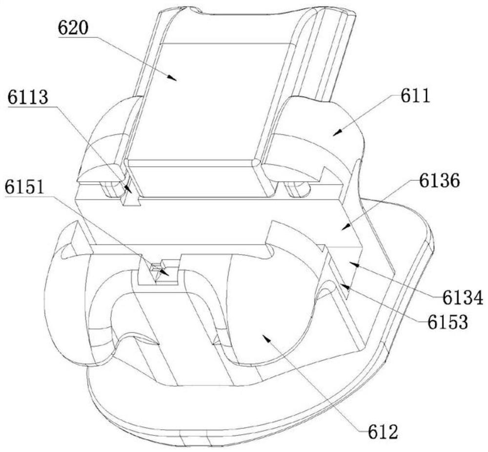
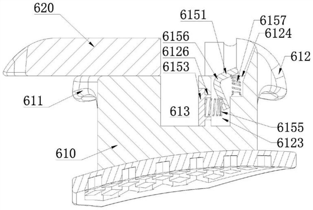
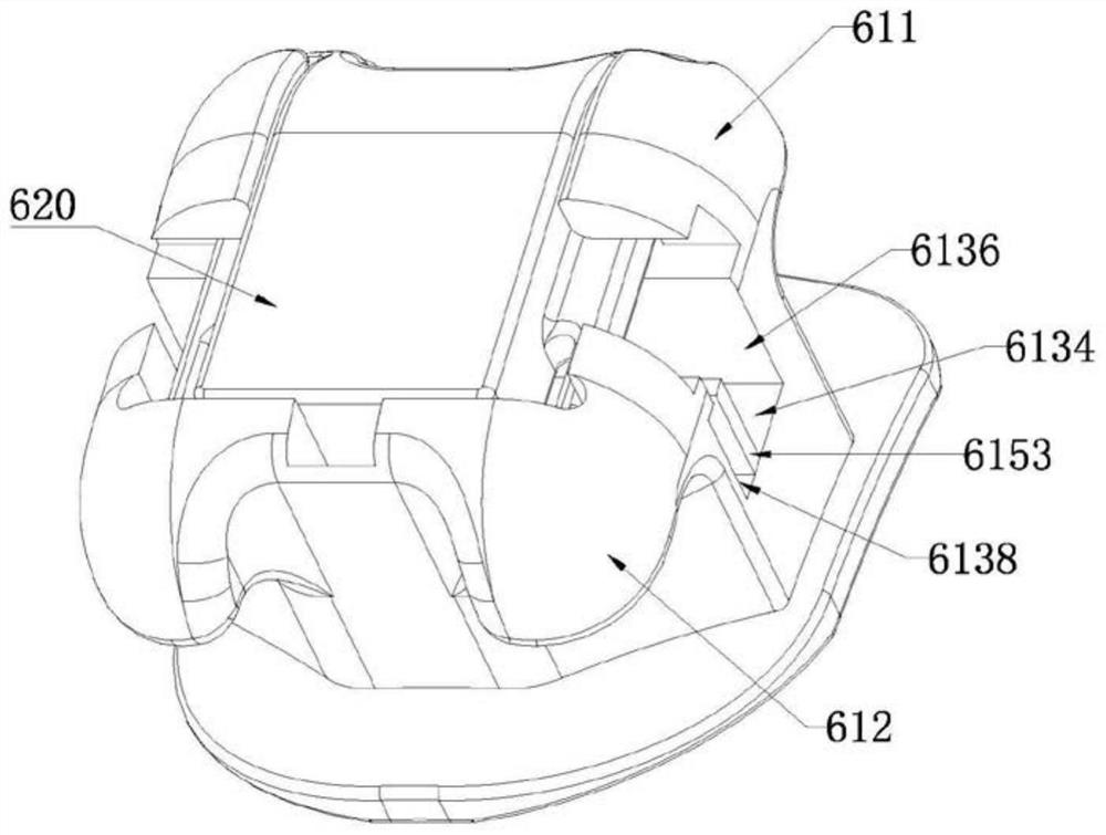
[0041] Such as Figure 1-Figure 4 As shown, an orthodontic bracket includes a bracket main body 610, a sliding cover 620 and a bottom plate. The bottom plate is arranged on the bottom of the bracket main body 610 for bonding with the tooth surface.

[0042] Specifically, the bracket main body 610 is provided with an archwire slot 613 and the limiting mechanism of Embodiment 1. The archwire slot 613 divides the bracket main body 610 into two, including a first bracket wing 611 protruding in the maxillary-gingiva direction. and a second bracket wing 612 protruding in the gingival-maxillary direction.

[0043] Wherein, the lip side of the first bracket wing 611 is provided with a receiving groove 6113 for accommodating the sliding cover 620 , and the two sides of the receiving groove 6113 are respectively provided with slide rails, and the slide rails are matched and slidably connected to the sliding cover 620 . The second bracket wing 612 is provided with an accommodating cavi...

Embodiment 2

[0056] Such as Figure 5-Figure 8 As shown, an orthodontic bracket includes a bracket main body 810, a screw cover 820 and a bottom plate. The bottom plate is arranged on the bottom of the bracket main body 810 for bonding with the tooth surface.

[0057] Specifically, the bracket main body 810 is provided with an archwire slot 813 and the limiting mechanism of Embodiment 2, the archwire slot 813 divides the bracket main body 810 into two, and includes a first bracket wing 811 protruding in the maxillary-gingiva direction. and a second bracket wing 812 protruding in the gingival-maxillary direction.

[0058] Wherein, the middle part of the lip side of the first bracket wing 811 is recessed to form a first accommodating cavity 8113 , and the first accommodating cavity 8113 accommodates the pivoting portion of the screw cap 820 . The second bracket wing 812 is provided with a second accommodating cavity 8123 for placing the limiting mechanism and a buckling position 8121 for m...


PUM


Abstract

The invention discloses a limiting mechanism of an arch wire slot and an orthodontic bracket applying the limiting mechanism. The limiting mechanism comprises a driving component arranged in a bracketmain body and a space occupying component arranged in the arch wire slot; the driving component is in transmission connection with the space occupying component; and the driving component is linked with open and close of a cover body of the orthodontic bracket so as to drive the space occupying component to move in the direction toward the gingival jaw in the arch wire slot. The limiting mechanism is linked with the cover body of the orthodontic bracket so as to adjust the arch wire accommodating space of the arch wire slot, when the cover body is closed, the limiting mechanism can be used for reducing the arch wire accommodating space in the arch wire slot and reducing the clearance of the arch wire slot, so that torque precise expression of arch wires can be ensured, and the orthodonticeffect of the orthodontic bracket applying the limiting mechanism is reinforced, and when the cover body is opened, the arch wire accommodating space can be restored to the original size by the archwire slot, and an enough space is provided for in and out of an arch wire.

Description

technical field [0001] The invention relates to the field of dental orthodontic treatment equipment, in particular to a limiting mechanism of an arch wire slot and an orthodontic bracket applied thereto. Background technique [0002] Orthodontic brackets are generally used in orthodontic treatment to move one or more teeth in a patient's dentition from an initial position to a desired position, and elastic archwires are usually used to connect the brackets for growing the teeth toward the desired position. Apply force over time. [0003] However, there is generally a problem in the existing orthodontic brackets: the size of the arch wire is generally smaller than the size of the arch wire slot. It is difficult for the arch wire to enter / exit the slot; and the size of the arch wire is smaller than the size of the arch wire slot, which will inevitably leave a gap between the inner wall of the arch wire slot and the arch wire, which directly affects the accurate expression of ...

Claims


Application Information

Patent Timeline
Patent Type & Authority Applications(China)
IPC IPC(8): A61C7/30A61C7/28
CPCA61C7/30A61C7/287A61C7/285
Inventor 张钦辉
Owner GUANGZHOU OO MEDICAL SCI LTD
Learn More