
Controlled drainage structure and method for emergency treatment of barrier lake

A technology of emergency treatment and discharge trough, which is applied in barrage/weir, water conservancy engineering, sea area engineering, etc. It can solve the problems of destructive impact on downstream bridges, poor disposal effect of barrier lakes, and not very successful, so as to prolong the collapse time, reduce submerged height and scour range, and reduce damage and loss effects

Pending Publication Date: 2019-05-28
HYDRAULIC SCI RES INST OF SICHUAN PROVINCE
View PDF0 Cites 10 Cited by
  • Summary
  • Abstract
  • Description
  • Claims
  • Application Information

AI Technical Summary

Problems solved by technology

For example, in 2018, the artificial disposal of the "11.03" barrier lake in the upper reaches of the Jinsha River resulted in a flood of 32,000 cubic meters per second, far exceeding the once-in-10,000-year flood. The result was a devastating impact on downstream bridges, and some power stations also suffered undue damage. losses, so the disposal of the barrier lake was not very successful
Another example is the Tibet Yigong landslide barrier lake formed on April 9, 2000. It collapsed on June 10, forming a storage capacity of about 2.88 billion cubic meters. Due to lack of disposal experience, only the barrier body with a height of 60 meters and a length of 2,500 meters The discharge trough was excavated above, so that the peak flow rate of the burst water caused by artificial drainage reached 1.2×10 5 Billion m 3 / s, the unprecedented massive flood wiped out the original Yigong Lake, causing considerable losses in the downstream, and the disposal effect of the barrier lake is poor and the safety is low

Method used


Image

  • Controlled drainage structure and method for emergency treatment of barrier lake
  • Controlled drainage structure and method for emergency treatment of barrier lake
  • Controlled drainage structure and method for emergency treatment of barrier lake

Examples


Embodiment Construction

[0024] The present invention will be further described below in conjunction with accompanying drawing.

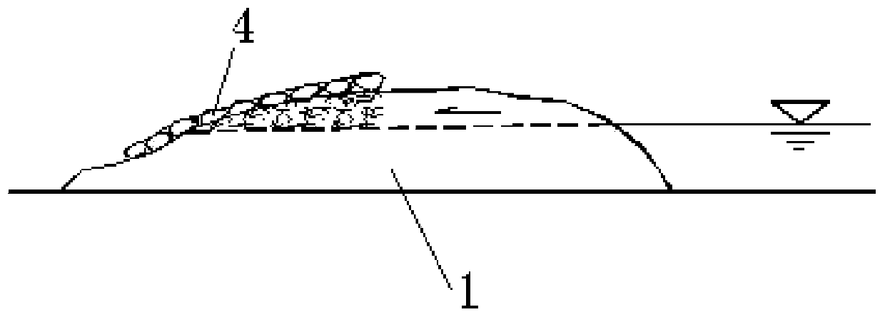
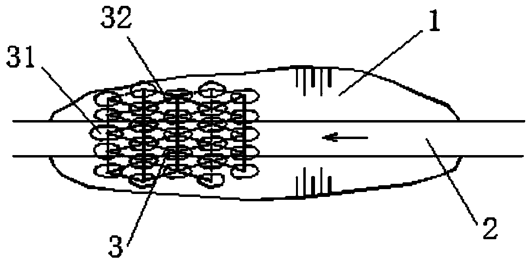
[0025] Such as figure 1 , figure 2 As shown, the present invention includes a discharge groove 2, which is located at the middle and lower part of the dam body 1 along the water flow direction, and also includes an anti-scouring structure 3, which is arranged in the discharge groove 2.

[0026] The function of the anti-scouring structure 3 is to hinder the water flow in the discharge groove 2, reduce the impact force of the water flow, reduce the peak value and velocity of the water flow, and prolong the discharge time. The cross-sectional shape of the discharge groove 2 is preferably rectangular, triangular, or trapezoidal. In order to set up the anti-scour structure 3 quickly, conveniently and at low cost, the anti-scour structure 3 is composed of a plurality of blocks 31 around the dammed lake, that is, the blocks 31 are existing on the dam body 1, and are directly pa...


PUM


Abstract

The invention relates to the technical field of emergency treatment of a barrier lake, in particular to a controlled drainage structure and method for emergency treatment of a barrier lake. The controlled drainage structure for emergency treatment of the barrier lake comprises a drainage channel and an anti-scouring structure, wherein the drainage channel is arranged on the middle lower portion ofa damming object in the water flow direction; and the anti-scouring structure is arranged in the drainage channel. When water of the barrier lake flows into the drainage channel, the anti-scouring structure obstructs the water flow in the drainage channel, the impact force of the water flow is reduced, the peak value and the flow speed of the water flow are effectively reduced, the burst time ofthe damming object caused by drainage scouring is prolonged, inundation height and scouring range along the lower reaches of the river are also reduced, damage and loss of the downstream are reduced as much as possible, and protection of a downstream ecological environment is improved. Visibly, according to the drainage structure and method for treatment of the barrier lake, the structure is simple, the treatment effect is good, the water quantity and flow speed of the drainage channel are controlled, and the safety of treatment of the barrier lake is improved remarkably.

Description

technical field [0001] The invention relates to the technical field of emergency disposal of barrier lakes, in particular to a discharge control structure and method for emergency disposal of barrier lakes. Background technique [0002] Secondary disasters such as floods and submersions caused by the breach of the barrier lake have a major adverse impact on the safety of life and property along the banks of the downstream river and on social and economic development. Generally, two types of disposal methods are adopted for the disposal of barrier lakes. One is the artificial passive disposal method, that is, for some small or less threatening barrier lakes, the method of artificial non-intervention is generally adopted, and they are allowed to collapse naturally. Only by strengthening monitoring, forecasting and other methods, the prerequisite for the disposal of this type of barrier lake is that the natural collapse will not have harmful or adverse effects on human society,...

Claims


Application Information

Patent Timeline
IPC IPC(8): E02B8/06
Inventor 梁军
Owner HYDRAULIC SCI RES INST OF SICHUAN PROVINCE
Learn More