
Coating device

A coating device and coating technology, which is applied to the device and coating of the surface coating liquid, can solve the problems of poor slurry uniformity and difficult control of product quality, and achieve the effect of high product quality and good coating uniformity

Active Publication Date: 2021-01-19
安徽富印新材料股份有限公司
View PDF12 Cites 1 Cited by
  • Summary
  • Abstract
  • Description
  • Claims
  • Application Information

AI Technical Summary

Problems solved by technology

[0003] The purpose of the present invention is to provide a coating device, aiming to solve the technical problem in the prior art that the base material is artificially sprayed with slurry, resulting in poor uniformity of the slurry covered on the surface of the base material, resulting in difficulty in controlling the quality of the product

Method used


Image

  • Coating device
  • Coating device
  • Coating device

Examples


Embodiment Construction

[0027] Embodiments of the present invention are described in detail below, examples of which are shown in the drawings, wherein the same or similar reference numerals designate the same or similar elements or elements having the same or similar functions throughout. The embodiments described below by referring to the figures are exemplary and are intended to explain the embodiments of the present invention and should not be construed as limitations of the present invention.

[0028] In the description of the embodiments of the present invention, it should be understood that the terms "length", "width", "upper", "lower", "front", "rear", "left", "right", "vertical ", "horizontal", "top", "bottom", "inner", "outer" and other indicated orientations or positional relationships are based on the orientations or positional relationships shown in the drawings, and are only for the convenience of describing the embodiments of the present invention and simplifying Describes, but does no...


PUM


Abstract

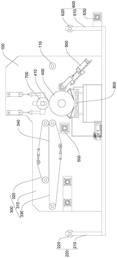
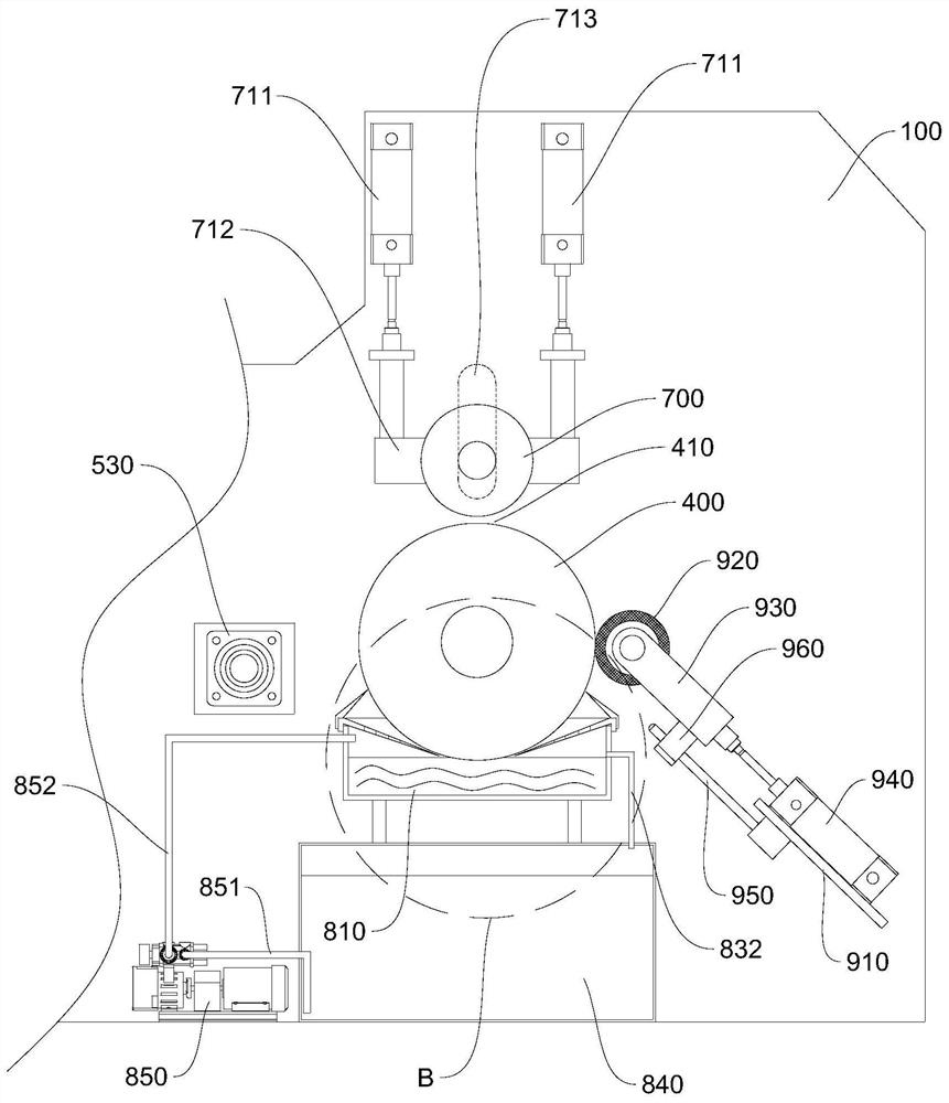
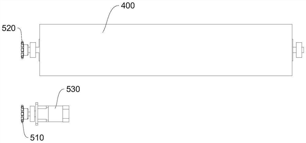
The invention belongs to the technical field of coating machinery, and particularly relates to a coating device. The coating device comprises a rack, a material containing frame, a conveying mechanism, a coating embossing roller and a receiving frame, wherein the material containing frame, the conveying mechanism, the coating embossing roller and the receiving frame are sequentially arranged on the rack. The two ends of the coating embossing roller are rotationally connected to the two sides of the rack, and the coating embossing roller is driven by a coating embossing roller driving mechanismto rotate. A positioning roller is arranged at the position, above the coating embossing roller, of the rack, and a coating gap is formed between the positioning roller and the coating embossing roller. A slurry mechanism is arranged at the position, below the coating embossing roller, of the rack. The slurry mechanism comprises a slurry containing box. A liquid groove communicating with the slurry containing box is formed in an upper cover of the slurry containing box, and the upper cover of the slurry containing box forms two first slurry scrapers on the two sides of the liquid groove correspondingly. The lower side of the coating embossing roller stretches into the liquid groove and is immersed into slurry in the slurry containing box, and a first slender liquid passing gap is formed between each first slurry scraper and the outer wall of the coating embossing roller. A coiled base material placed on the material containing frame sequentially penetrates through the conveying mechanism and the coating gap to be connected to the receiving frame.

Description

technical field [0001] The invention belongs to the technical field of coating machinery, and in particular relates to a coating device. Background technique [0002] Rolled substrates (such as cloth, paper, leather) need to be coated with a layer of glue, paint or ink with specific functions on their surface. In the prior art, workers use liquid spray equipment to spray the slurry on the surface of the substrate, so that the surface of the substrate is covered with a layer of slurry, but this processing method has the following disadvantages: when spraying manually, the worker sprays on the surface of the substrate The amount of slurry is not easy to control, so that the spray uniformity of the slurry covered on the surface of the substrate is poor, resulting in the quality of the product is difficult to control; at the same time, spraying will cause a large amount of liquid mist, which is easy to spread in the environment and cause pollution to the surrounding environment ...

Claims


Application Information

Patent Timeline
Patent Type & Authority Applications(China)
IPC IPC(8): B05C1/08B05C1/12B05C13/02
CPCB05C1/0813B05C1/0817B05C1/0821B05C1/12B05C13/02
Inventor 岳刚
Owner 安徽富印新材料股份有限公司
Learn More