Temporary distribution box building device

A distribution box and temporary technology, applied in the substation/distribution device casing, substation/switch layout details, electrical components, etc., can solve the problem of difficult and rapid construction, and achieve the effect of convenient access and simple method.

Active Publication Date: 2021-01-19
GUANGDONG POWER GRID CO LTD +1
View PDF4 Cites 2 Cited by
  • Summary
  • Abstract
  • Description
  • Claims
  • Application Information

AI Technical Summary

Problems solved by technology

[0003] The purpose of the present invention is to provide a temporary distribution box construction device to solve the problem that it is difficult to quickly build multiple temporary distribution boxes that can facilitate the installation of electrical components and facilitate the acquisition of materials

Method used


Image

  • Temporary distribution box building device
  • Temporary distribution box building device

Examples


Embodiment 1

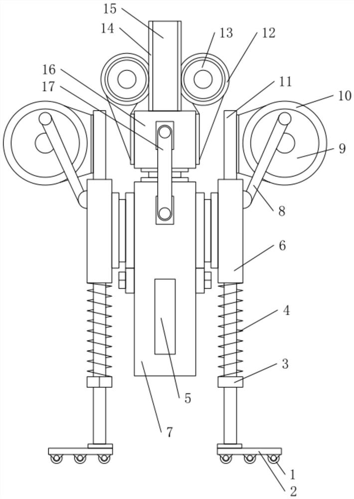
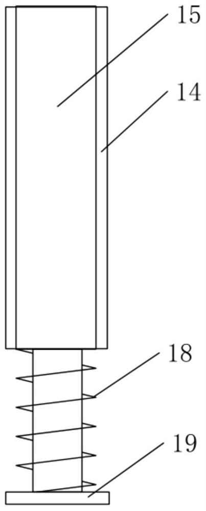
[0031] Such as figure 1 with figure 2 As shown, in this embodiment, the temporary distribution box construction device includes an insertion socket 7 , a push rod 19 , a driving mechanism, a guide rod 11 , a lifting mechanism and a second elastic member 4 . Wherein: the bottom end of inserting sleeve 7 is provided with opening, and push rod 19 slides and is placed in inserting sleeve 7, and driving mechanism is used for driving ejector rod 19 to slide up and down in inserting sleeve 7, and inserting sleeve 7 slides and is arranged on guide rod 11, guides The rod 11 extends vertically, and the insert 7 can slide relative to the guide rod 11 to have a first position and a second position. When the insert 7 is in the first position, the insert 7 is far away from the ground, and when the insert 7 is in the second position, the opening of the insertion socket 7 is inserted into the ground, the lifting mechanism is used to drive the insertion socket 7 to move from the second posit...

Embodiment 2

[0043] Embodiment 2 is the same as Embodiment 1 except for the lifting mechanism. The lifting mechanism in Embodiment 2 includes a first driving member, a gear and a rack. The first driving member is fixedly installed on the guide rod, and the gear is a half-circle toothed gear. , the gear is fixedly installed on the output end of the first driving member, the rack is fixedly installed on the first guide cylinder, and the rack and the gear mesh. The first driving part starts to drive the gear with only half a circle to rotate. When the toothed area of ​​the gear is opposite to the rack, the gear drives the rack to move upward, and the rack drives the first guide cylinder to slide upward along the guide rod, and at the same time stretches the first guide cylinder. An elastic member, the first guide cylinder drives the inserting cylinder to move from the position inserted into the ground to a position away from the ground, when the toothless area of ​​the gear is opposite to the ...

Embodiment 3

[0045] Embodiment 3 is the same as Embodiment 1 except for the driving mechanism. In Embodiment 3, the driving mechanism includes a cylinder and a push rod, the cylinder is fixedly installed on the second guide cylinder, the push rod is driven and matched with the cylinder, and the push rod is fixedly connected to the ejector sleeve . The cylinder drives the push rod to move downward, and the push rod drives the ejector sleeve to move downward, making it compress the first elastic member and drive the ejector rod to slide downward in the insert, pushing out the soil column formed in the insert.


PUM


Abstract

The invention belongs to the technical field of power distribution boxes, and discloses a temporary power distribution box building device which comprises an insertion cylinder with an opening at thebottom end; an ejector rod which is arranged in the inserting cylinder in a sliding manner; a driving mechanism which is used for driving the ejector rod to slide up and down in the inserting cylinder; a guide rod, wherein the inserting cylinder is arranged on the guide rod in a sliding mode, the guide rod extends in the vertical direction, the inserting cylinder can slide relative to the guide rod and has a first position and a second position, when the inserting cylinder is located at the first position, wherein the inserting cylinder is away from the ground; when the inserting cylinder is located at the second position, an opening of the inserting cylinder is inserted into the ground; a lifting mechanism which is used for driving the inserting cylinder to move from the second position to the first position; a second elastic piece which is used for driving the inserting cylinder to move from the first position to the second position. According to the device, soil is used as a material for setting up the temporary distribution box, taking and using are convenient, the mode of setting up the temporary distribution box is simple, and multiple temporary distribution boxes facilitating installation of electrical apparatus elements can be quickly set up.

Description

technical field [0001] The invention relates to the technical field of distribution boxes, in particular to a temporary distribution box construction device. Background technique [0002] The distribution box is a functional device that reasonably distributes electric energy and facilitates the user to open and close the circuit. It has a high level of safety protection and can intuitively display the conduction state of the circuit. The common distribution box body is made of steel or wood. The box body is high in strength but heavy, and it is time-consuming and laborious to transport. It is necessary to build a temporary distribution box when temporarily using electricity outdoors, but the materials required for building a temporary distribution box outdoors It is not easy to find, and it is inconvenient to install electrical components in the temporary distribution box, and it is not easy to quickly build multiple distribution boxes, which is seriously time-consuming and ...

Claims


Application Information

Patent Timeline
Patent Type & Authority Applications(China)
IPC IPC(8): H02B1/50H02B1/52H02B1/28
CPCH02B1/28H02B1/505H02B1/52
Inventor 沈瑞锡黄日光吴贻标陈文其肖晓慧曹贵阳谭世钊叶康黄伟华温可良郭思威朱洪彬彭林伟劳文旭陈顺发
Owner GUANGDONG POWER GRID CO LTD
Why Eureka
Try Eureka