Lock slider for slide fastener

A sliding head, lockable technology, applied in the direction of sliding fastener elements, applications, fasteners, etc., can solve problems such as being easily damaged, the locking element cannot be smoothly guided, and the sliding head is difficult to achieve rigidity.

Inactive Publication Date: 2003-10-01
YKK CORP
View PDF1 Cites 1 Cited by
  • Summary
  • Abstract
  • Description
  • Claims
  • Application Information

AI Technical Summary

Problems solved by technology

In addition, since the front and rear walls of the opening 15" of the upper wing 3" have sharp edges, the upper surface of the latch, especially the braid or sewing thread, is easily damaged due to the movement of the sliding head.
[0007] In addition, on the one hand, because the width of one end of the opening 15 "is larger than that of the locking pawl 23", on the other hand, because the width of the front end of the sliding head body 1 "is larger than the rear end in the same shape as the upper wing 3 ", the locking member cannot be smoothly guide
And because the connecting ring 22 "of the pull piece 2" is respectively connected to the two lateral protrusions 14" of the pull piece connection lug 11" with threads, the pull piece 2" cannot be firmly connected.
Also, since there is only one lateral flange 6" spanning the upper wing around the opening 15", it is difficult to achieve the proper stiffness of the slider.

Method used


Image

  • Lock slider for slide fastener
  • Lock slider for slide fastener
  • Lock slider for slide fastener

Examples


Embodiment Construction

[0032] The preferred embodiments of the lockable sliding head for zipper according to the present invention will be described in detail below with reference to the accompanying drawings.

[0033] As shown in Figures 5 and 6, the lockable slider of the present invention can be worn on the following types of zippers (ziplock), for example, with two rows of braid B and sewing thread S sewn across the zipper tape 7 A type in which the continuous fasteners E on the inner longitudinal sides of the zipper tape T and each row is composed of a zigzag-shaped monofilament, or two rows are installed on the inner longitudinal length of the zipper tape T by molding or nail The type of discrete locks on the side.

[0034] In addition, the lockable slider can also be used for a type of zipper (zip) that has two rows of looped or zigzag-shaped fasteners and each row is mounted on one surface of the zipper tape.

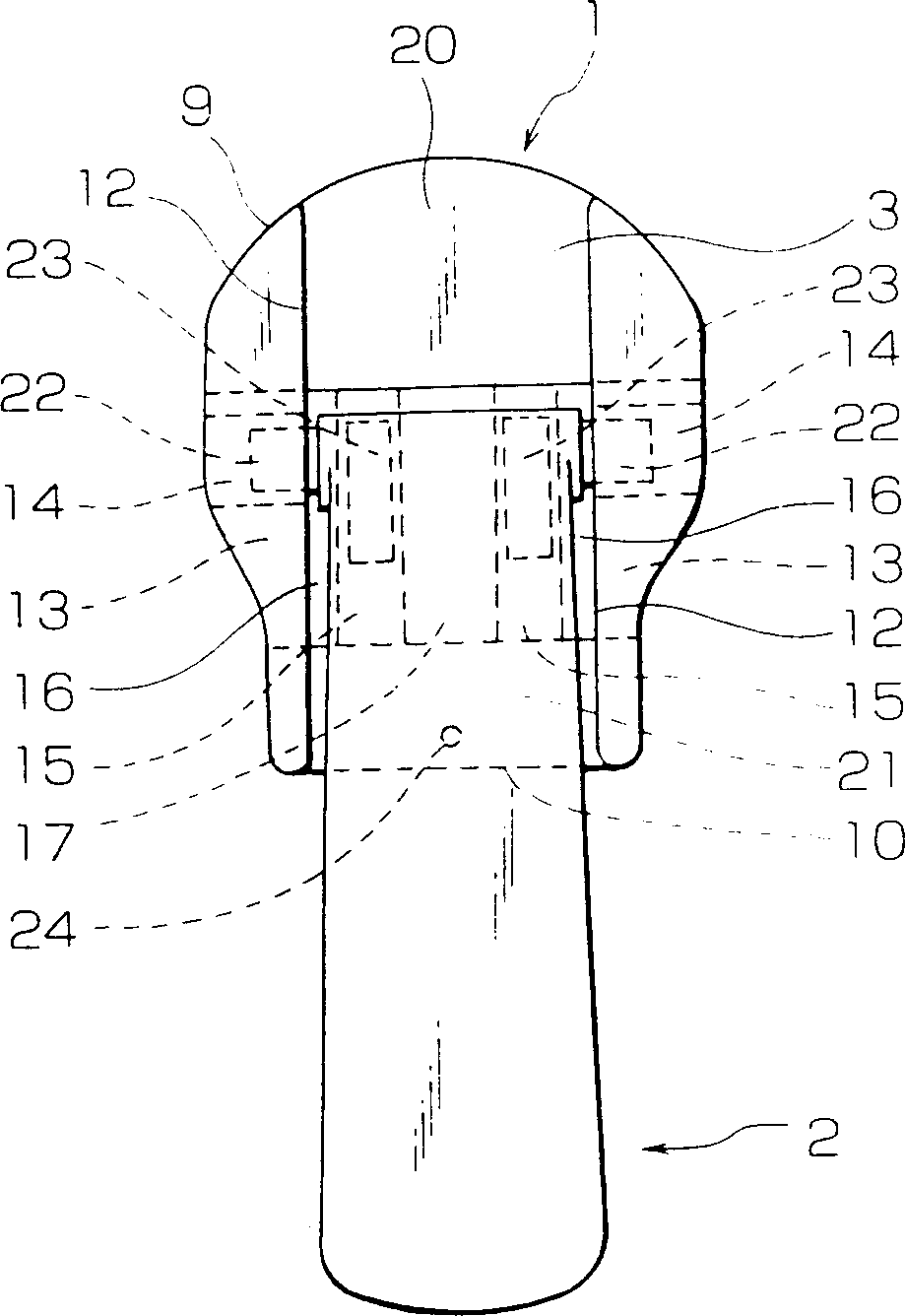
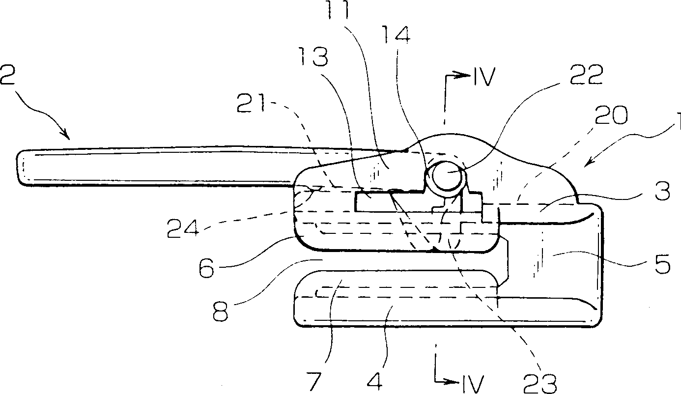
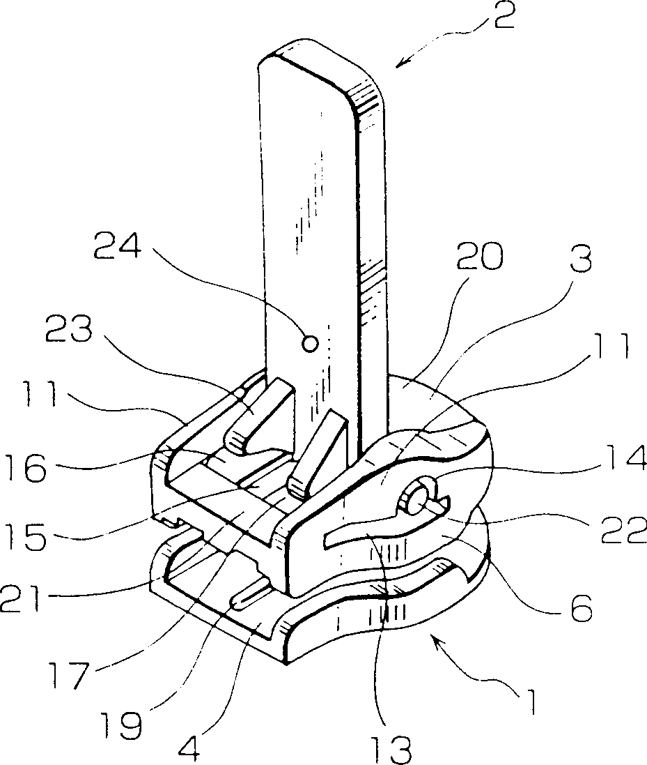
[0035] As shown in FIGS. 1 to 4, the lockable slider according to the present inventi...


PUM


Abstract

A lockable sliding head for a zipper has: a sliding head body formed by connecting upper and lower wings at its front end, and the upper wing has a pair of downwardly and upwardly protruding side flanges on its lower and upper surfaces respectively And lugs, the lugs are provided with horizontal grooves and connected pivot insertion holes, and the upper wing also has locking pawl insertion holes connected with the horizontal grooves; a pull tab has a pair of lateral pivots at its base that can be inserted into the The pivot is inserted into the hole, and at least one locking pawl is provided on one surface thereof to be inserted into the locking pawl insertion hole. During production, the slider body and the pull piece can be simultaneously molded out in an assembled form using cores that can be moved in from the front, rear, left, right, upper and lower sides.

Description

Technical field [0001] The present invention relates to a lockable sliding head (lock head) for a zipper, and more specifically to a lockable sliding head. The sliding head is composed of a pull tab with a locking pawl and a sliding head body in an assembled form Simultaneously molded out. Background technique [0002] As shown in Figure 10, Japanese Utility Model Bulletin No. 51-4809 has disclosed a traditional lockable sliding head for zipper, in which a pull tab that opens backward is opened in the center of the upper surface of the sliding head body. The groove 12' can receive the pull tab 2'therein so that the upper surface of the pull tab 2'is flush with the upper surface of the sliding head body 1'. When assembling, a pair of side pivots 22' of the pull tab 2'are received in the pull tab clamping groove 14', and the grooves 14' are provided on two opposite walls of the pull tab slot 12' Extending from the rear end of the slider body 1'to a central position, the two mutuall...

Claims


Application Information

Patent Timeline
IPC IPC(8): A44B19/30
CPCA44B19/305Y10T24/2568Y10T24/2586A44B19/26A44B19/30
Inventor 若林政男
Owner YKK CORP
Why Eureka
Try Eureka