
Docking optical guide device

A guiding device and optical technology, applied in the optical field, can solve the problems of button wear and unusability, etc.

Pending Publication Date: 2021-01-22
上海中船船舶设计技术国家工程研究中心有限公司
View PDF0 Cites 0 Cited by
  • Summary
  • Abstract
  • Description
  • Claims
  • Application Information

AI Technical Summary

Problems solved by technology

[0004] The purpose of the present invention is to provide a docking optical guiding device, which can effectively achieve the effect of closing the circuit through the induction of the magnetic field by the Hall switch, and solve the technical problem that the enable button is worn out and cannot be used after being pressed for a long time

Method used


Image

  • Docking optical guide device
  • Docking optical guide device
  • Docking optical guide device

Examples


Embodiment Construction

[0043] The following will clearly and completely describe the technical solutions in the embodiments of the present invention with reference to the accompanying drawings in the embodiments of the present invention. Obviously, the described embodiments are only some, not all, embodiments of the present invention. Based on the embodiments of the present invention, all other embodiments obtained by persons of ordinary skill in the art without creative efforts fall within the protection scope of the present invention.

[0044] It should be noted that, in the case of no conflict, the embodiments of the present invention and the features in the embodiments can be combined with each other.

[0045] The present invention will be further described below in conjunction with the accompanying drawings and specific embodiments, but not as a limitation of the present invention.

[0046] The invention provides a docking optical guiding device, which belongs to the field of optics, such as f...


PUM


Abstract

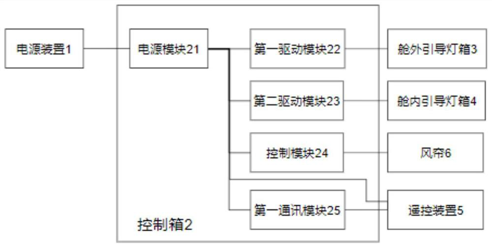
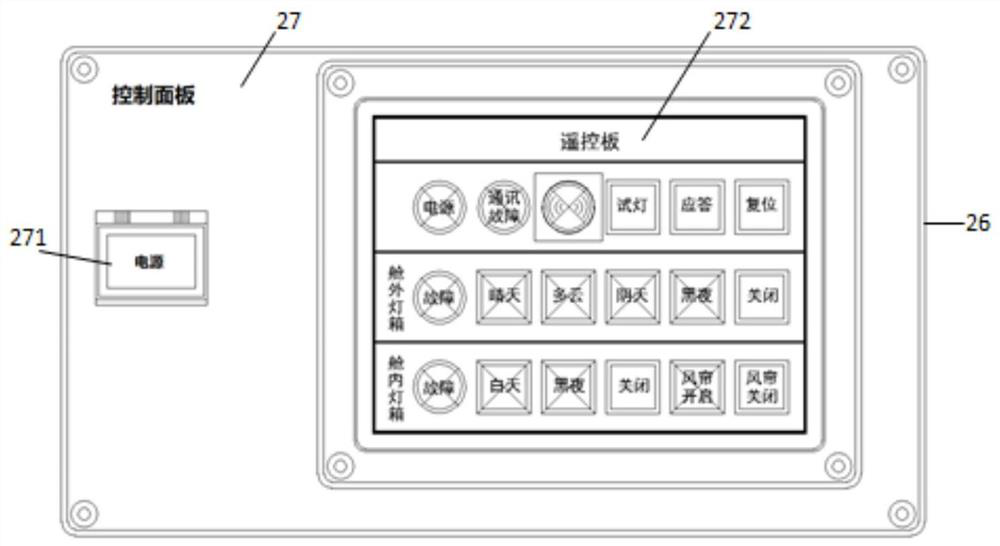
The invention discloses a docking optical guide device, and belongs to the field of optics. The device comprises an out-cabin guide lamp box, an in-cabin guide lamp box, a control box, a remote control device, an air curtain and a power supply device, wherein each of the out-cabin guide lamp box and the in-cabin guide lamp box comprises a main grating module, an indication grating module, a box body, a light source module and a reflector module which are connected in sequence; and the control box is connected with the out-cabin guiding lamp box, the in-cabin guiding lamp box, the remote control device and the power supply device and comprises a box body, a door plate, a first driving module, a second driving module, a first communication module, a control module and a power supply module.The docking optical guide device based on the optical molar effect has the beneficial effects that the docking optical guide device based on the optical molar effect can meet the guiding and using requirements of an air cushion landing boat under the environment conditions of sunny days, cloudy days, cloudy days, dusk, night and the like, is high in reliability and convenient to install, replace and maintain, and meets the shipping and using conditions.

Description

technical field [0001] The invention relates to the field of optics, in particular to a docking optical guiding device. Background technique [0002] The air cushion landing craft mainly uses a high-power fan to quickly press a large amount of air into the bottom of the hull, so that a high-pressure air mass is formed between the bottom of the hull and the ground, and the entire hull is lifted off the ground. In this way, it is as if a flowing air cushion is added between the hull and the ground, which reduces the forward resistance. The forward power is generally obtained by blowing the air backwards by the fan on the hull, so that the boat can be on the beach, in the mud, Landing and driving on relatively flat terrain such as swamps, water net rice fields, and ice and snow. The ship is fast and capable of landing and driving. It can sail at a certain height above the water surface and land on relatively flat terrain, and can cross obstacles equivalent to about 70% of the ...

Claims


Application Information

Patent Timeline
IPC IPC(8): B63C1/12F21S8/00F21V8/00F21V23/00F21V7/22F21V11/00F21W107/20
CPCB63C1/12F21S8/00F21V7/22F21V11/00F21V23/003F21V2200/00F21W2107/20
Inventor 唐钧杰王全虎方钰亨林嘉昊刘洋
Owner 上海中船船舶设计技术国家工程研究中心有限公司
Learn More