Gas-liquid separation device for sodium hypochlorite generator

A gas-liquid separation device, sodium hypochlorite technology, applied in separation methods, liquid degassing, chemical instruments and methods, etc., can solve the problems of liquid level fluctuations, large fluctuations, and reduced current efficiency, so as to save electricity costs, No pressure operation, small size effect

Active Publication Date: 2022-04-26
SUNRUI MARINE ENVIRONMENT ENG
View PDF38 Cites 1 Cited by
  • Summary
  • Abstract
  • Description
  • Claims
  • Application Information

AI Technical Summary

Problems solved by technology

The existing problem is: if the hydrogen gas produced in the electrolysis process is not discharged in time and effectively, the hydrogen gas will flow with the electrolyte in the electrolytic cell, increasing the impedance of the electrolyte and reducing the current efficiency; at the same time, too much hydrogen accumulation will also cause It affects the stable operation of the generator, so it is necessary to use a gas-liquid separation device to discharge hydrogen
This kind of exhaust valve is greatly affected by the pressure in the gas-liquid separation tank. When the pressure in the separation tank is high, the corresponding counterweight will increase, and when the pressure in the separation tank is low, the counterweight will decrease. Therefore, only Can correspond to a stable working condition
Moreover, the valve ball of the exhaust valve moves up and down very frequently and fluctuates greatly, causing the liquid level in the gas-liquid separation tank to fluctuate frequently.

Method used


Image

  • Gas-liquid separation device for sodium hypochlorite generator
  • Gas-liquid separation device for sodium hypochlorite generator
  • Gas-liquid separation device for sodium hypochlorite generator

Examples


no. 1 example

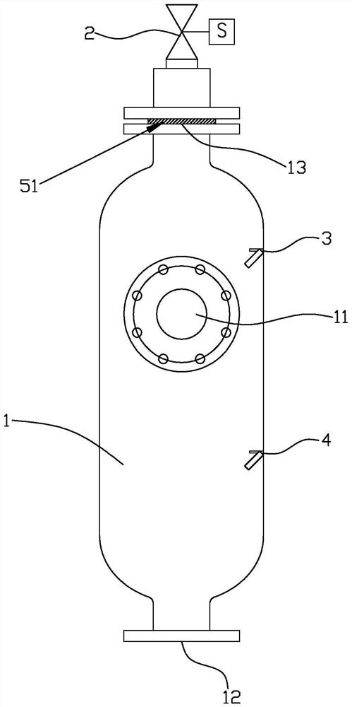
[0030] Such as Figure 1 to Figure 3 As shown, the gas-liquid separation device provided by the first embodiment of the present invention can be applied to the gas-liquid separation of the electrolysis product (sodium hypochlorite solution and hydrogen) of the sodium hypochlorite generator, and can quickly discharge the by-product hydrogen in the sodium hypochlorite solution.

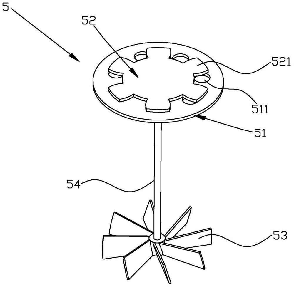
[0031] The gas-liquid separation device comprises a gas-liquid separation tank 1, the side wall of the gas-liquid separation tank 1 is provided with an inlet 11, the bottom of the gas-liquid separation tank 1 is provided with an outlet 12, and the top of the gas-liquid separation tank 1 is provided with an exhaust port 13 , the gas-liquid separation device also includes an exhaust assembly 5, and the exhaust assembly 5 includes an exhaust orifice plate 51, a rotating adjustment plate 52, a connecting rod 54 and a hydraulic rotating blade 53, and the exhaust orifice plate 51 is fixed on the bottom of the ...

no. 2 example

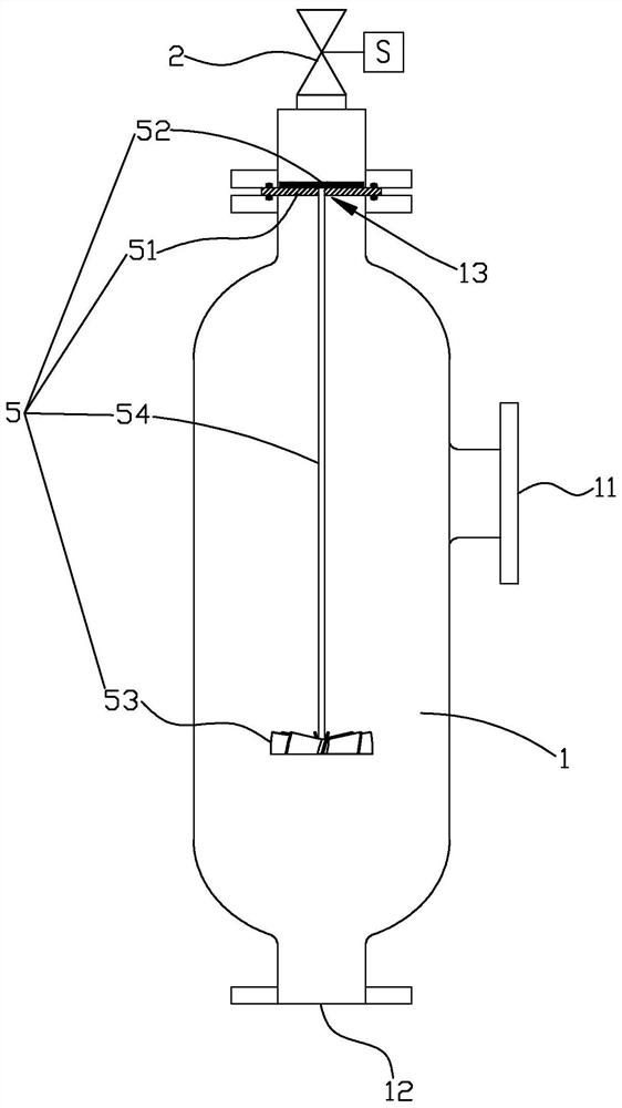
[0049] Such as Figure 6 and Figure 7 As shown, the gas-liquid separation device provided by the second embodiment of the present invention is basically the same as that of the first embodiment, except that the structure of the exhaust assembly 5 is different.

[0050] Specifically, in this embodiment, the top surface of the rotating adjustment plate 52 is attached to the bottom surface of the exhaust hole plate 51, the center of the exhaust hole plate 51 is provided with a first through hole 512, and the center of the rotation adjusting plate 52 A second through hole 522 is provided at the position, and the top end of the connecting rod 54 is inserted into the first through hole 512 after passing through the second through hole 522 , and the rotation adjusting plate 52 is fixedly connected with the connecting rod 54 through the second through hole 522 .

[0051] Preferably, a bearing 55 is disposed in the first through hole 512 , and the connecting rod 54 is inserted into t...

no. 3 example

[0054] Such as Figure 8 As shown, the gas-liquid separation device provided by the third embodiment of the present invention is substantially the same as that of the first embodiment, the difference is that this embodiment is also provided with a buffer tank 6 and a second exhaust solenoid valve 7, while the high liquid level sensor 3 It is different from the location where the low liquid level sensor 4 is set.

[0055] Specifically, in this embodiment, the gas-liquid separation device further includes a buffer tank 6 , the outlet 12 of the gas-liquid separation tank 1 protrudes into the buffer tank 6 , and a buffer tank outlet 61 is provided at the bottom of the buffer tank 6 .

[0056] Preferably, the gas-liquid separation device also includes a first exhaust solenoid valve 2, a high liquid level sensor 3 and a low liquid level sensor 4, the first exhaust solenoid valve 2 is arranged above the exhaust orifice plate 51, and the high liquid level sensor 3 and the low liquid ...


PUM


Abstract

The invention provides a gas-liquid separation device for a sodium hypochlorite generator, comprising a gas-liquid separation tank, the side wall of the gas-liquid separation tank is provided with an inlet, the bottom of the gas-liquid separation tank is provided with an outlet, and the gas-liquid separation tank is provided with an outlet. The top of the liquid separation tank is provided with an exhaust port, and the gas-liquid separation device also includes an exhaust assembly, which includes an exhaust orifice plate, a rotating adjustment plate, a connecting rod and a hydraulic rotating blade, and the exhaust hole The plate is fixed on the top of the gas-liquid separation tank and seals the exhaust port, the rotating adjustment plate is attached to the exhaust hole plate, and the top end of the connecting rod is fixed to the rotating adjusting plate connected, the bottom end of the connecting rod is fixedly connected with the hydraulic rotary blade, the hydraulic rotary blade is located in the gas-liquid separation tank, the exhaust hole plate is provided with an exhaust hole, and the rotary adjustment plate Driven by the hydraulic rotating vane, it rotates and covers or opens the exhaust hole, so that the ventilation area of ​​the exhaust hole changes.

Description

technical field [0001] The invention relates to the technical field of gas-liquid separation, in particular to a gas-liquid separation device for a sodium hypochlorite generator, and is also suitable for an electrolytic ballast water management system. Background technique [0002] The sodium hypochlorite generator is a device that uses electrodes to form an electrolytic chamber, uses dilute brine or seawater as raw material, and generates sodium hypochlorite solution and hydrogen after direct current electrolysis. The existing problem is: if the hydrogen generated during the electrolysis process is not discharged in time and effectively, the hydrogen will flow in the electrolytic cell with the electrolyte, increasing the impedance of the electrolyte and reducing the current efficiency; at the same time, excessive accumulation of hydrogen will also cause It affects the stable operation of the generator, so it is necessary to use a gas-liquid separation device to discharge hy...

Claims


Application Information

Patent Timeline
Patent Type & Authority Patents(China)
IPC IPC(8): B01D19/00C25B15/00C25B9/60C25B1/26
CPCB01D19/00C25B15/00C25B9/00C25B1/26
Inventor 徐凤麒尹国枫
Owner SUNRUI MARINE ENVIRONMENT ENG
Why Eureka
Try Eureka