Pipeline cutting equipment with supporting function

A pipe cutting and equipment technology, applied in the direction of shearing machine equipment, metal processing equipment, pipe shearing device, etc., can solve the problems of affecting pipe connection and uneven cutting surface, so as to improve friction, avoid vibration offset, and avoid deformation Effect

Active Publication Date: 2021-01-26
山东沂南园区开发建设有限公司
View PDF12 Cites 0 Cited by
  • Summary
  • Abstract
  • Description
  • Claims
  • Application Information

AI Technical Summary

Problems solved by technology

[0003] At present, there is a kind of equipment for pipe cutting with support function. During the process of cutting the pipe, the cutter in the cutting equipment quickly rubs against the pipe, causing

Method used


Image

  • Pipeline cutting equipment with supporting function
  • Pipeline cutting equipment with supporting function
  • Pipeline cutting equipment with supporting function

Examples


Embodiment 1

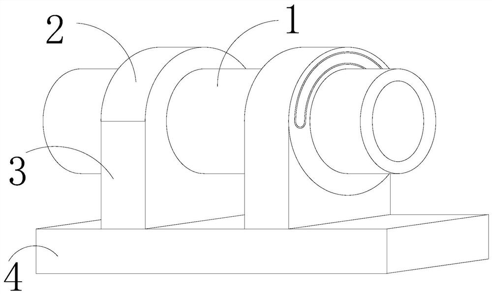
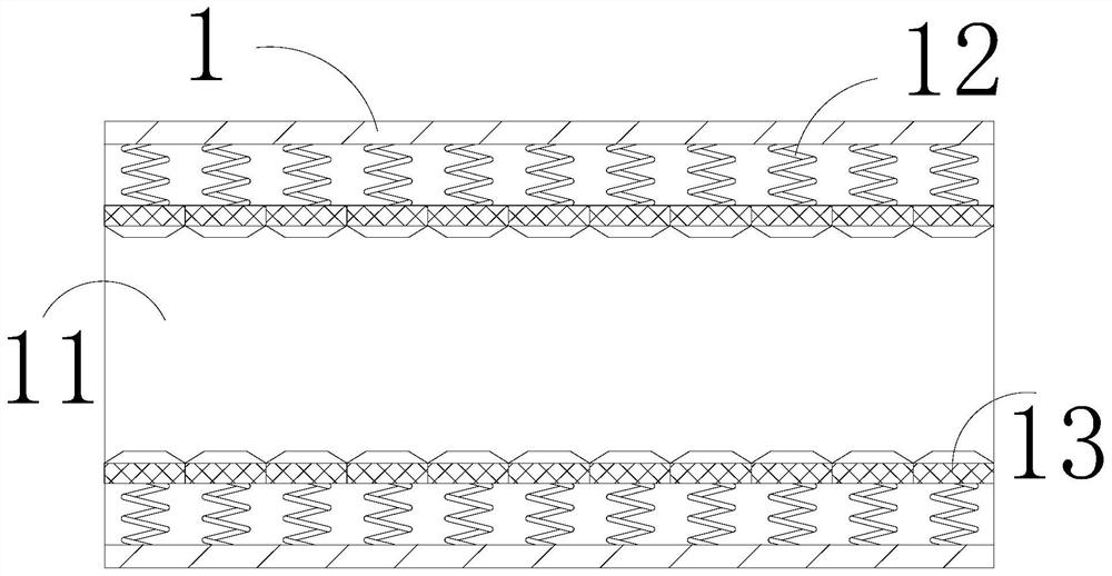
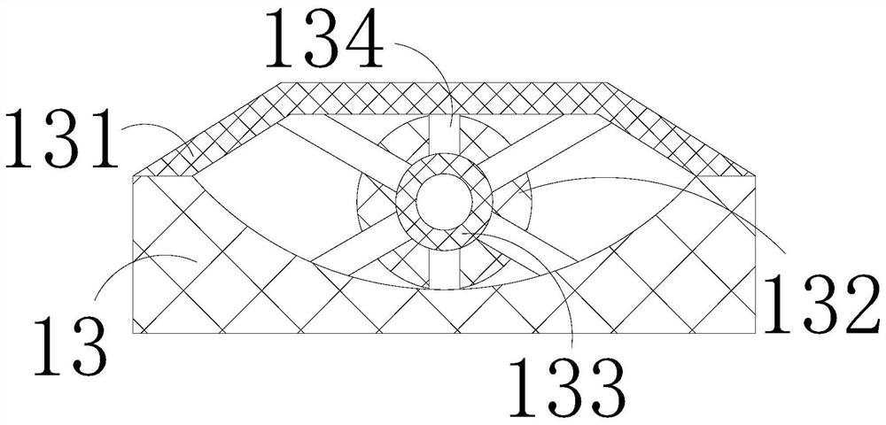
[0029] The present invention provides a pipe cutting equipment with support function, its structure includes a fixed cylinder 1, a cutter 2, a support plate 3, a base 4, the cutter 2 is nested in the outer periphery of the fixed cylinder 1, and the support plate 3 The upper surface is welded to the bottom of the fixed cylinder 1, the base 4 is connected to the bottom of the support plate 3 by welding, the fixed cylinder 1 includes a through pipe 11, a spring 12, and a clip 13, and the through pipe 11 is embedded in the fixed cylinder 1, one end of the spring 12 is embedded in the inner wall of the through pipe 11, and the clamp block 13 is connected to the other end of the spring 12 by welding. The left and right walls of 13 are smooth, and the thrust of the spring 12 to the clamp block 13 is greater than the gravity of the clamp block 13 itself, which is conducive to clamping the pipeline under the thrust of the spring 12 after the pipeline passes through the through pipe 11. ...

Embodiment 2

[0035] The present invention provides a pipe cutting equipment with support function, its structure includes a fixed cylinder 1, a cutter 2, a support plate 3, a base 4, the cutter 2 is nested in the outer periphery of the fixed cylinder 1, and the support plate 3 The upper surface is welded to the bottom of the fixed cylinder 1, the base 4 is connected to the bottom of the support plate 3 by welding, the fixed cylinder 1 includes a through pipe 11, a spring 12, and a clip 13, and the through pipe 11 is embedded in the fixed cylinder 1, one end of the spring 12 is embedded in the inner wall of the through pipe 11, and the clamp block 13 is connected to the other end of the spring 12 by welding. The left and right walls of 13 are smooth, and the thrust of the spring 12 to the clamp block 13 is greater than the gravity of the clamp block 13 itself, which is conducive to clamping the pipeline under the thrust of the spring 12 after the pipeline passes through the through pipe 11. ...


PUM


Abstract

The invention discloses pipeline cutting equipment with a supporting function. The pipeline cutting equipment structurally comprises a fixed barrel, a cutter, a supporting plate and a base, wherein the cutter is nested at the periphery of the fixed barrel; the upper surface of the supporting plate is welded with the bottom of the fixed barrel; and the base is connected to the bottom of the supporting plate by welding. The pipeline cutting equipment has the beneficial effects that: a clamping block and a spring are extruded in a through tube, the clamping block clamps the pipeline under elasticforce of the spring, and a rubber block increases friction force between the pipeline and the clamping block, so that the pipeline is prevented from vibrating and deviating in a cutting process to avoid an uneven cut surface at a cut of the pipeline; meanwhile, a brushing strip wipes the surface of the pipeline, so that dust impurities are prevented from being adhered on the surface of the pipeline to affect paving of the pipeline; a slide block slides on a slide rail back and forth, so that a tool cuts the pipeline back and forth; and a fixed block and a supporting column support a cutting plate, so that the cutting plate is prevented from being deformed.

Description

technical field [0001] The invention relates to the field of pipe cutting, in particular to a pipe cutting device with supporting function. Background technique [0002] Pipes have good conveying capacity and tightness, and are widely used in our lives. When laying pipes, use pipe cutting equipment to cut the pipes into appropriate lengths to facilitate the connection between pipes, and The pipe cutting equipment with supporting function has good stability during the cutting process. [0003] At present, there is a kind of equipment for pipe cutting with support function. During the process of cutting the pipe, the cutter in the cutting equipment quickly rubs against the pipe, causing the two ends of the pipe to vibrate continuously, so that the pipe is vibrated during the vibration process. The offset causes the cutting surface to be uneven after cutting, which affects the connection of the pipes. Contents of the invention [0004] Aiming at the existing equipment for p...

Claims


Application Information

Patent Timeline
IPC IPC(8): B23D21/04B23D33/02B08B9/023
CPCB08B9/023B23D21/04B23D33/02
Inventor 韩梦茹
Owner 山东沂南园区开发建设有限公司
Why Eureka
Try Eureka