Electric screwdriver
An electric screwdriver, screwdriver head technology, applied in screwdrivers, power tools, wrenches, etc., can solve problems such as inability to screw installation
- Summary
- Abstract
- Description
- Claims
- Application Information
AI Technical Summary
Problems solved by technology
Method used
Image

Examples
specific Embodiment approach 1
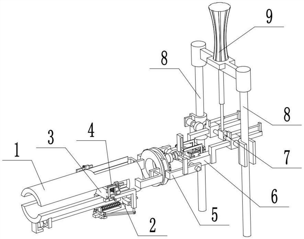
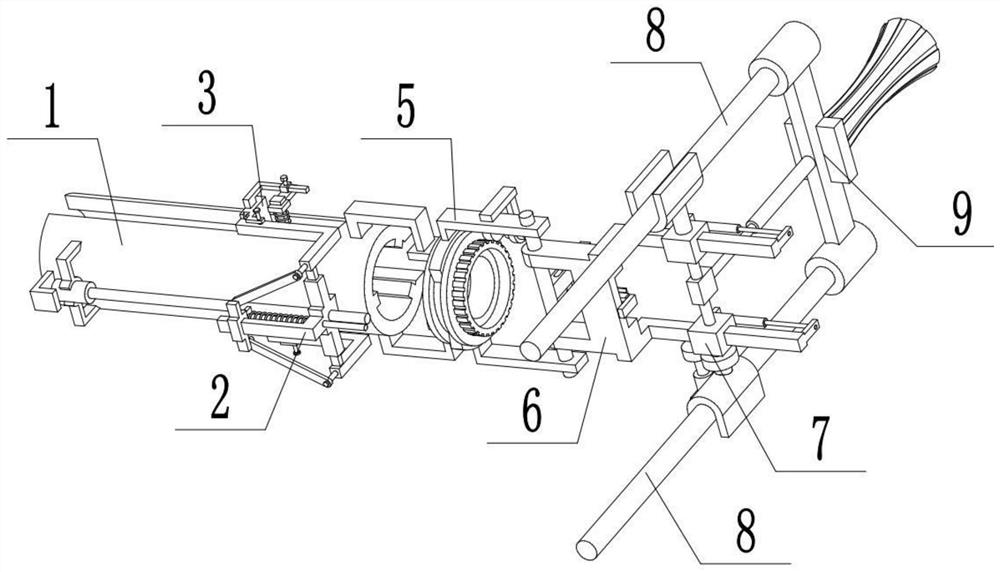
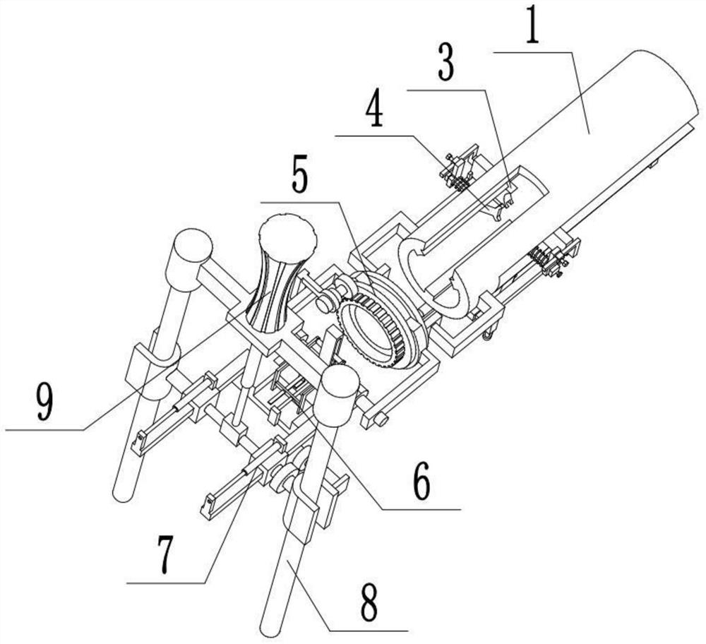
[0033] Combine below Figure 1-12 Describe this embodiment, an electric screwdriver, including a hollow screwdriver head 1, a screw feeder 2, a top plate 3, a block 4, a rotation control device 5, an angle control mechanism 6, a storage control member 7, a pole 8 and a handle 9 , the screw feeder 2 is set and connected to the lower end of the hollow screwdriver head 1, the two ends of the screw feeder 2 are respectively provided with a top plate 3, and the two top plates 3 are respectively movably connected to the two ends of the hollow screwdriver head 1 , the two top plates 3 are respectively connected with a block 4, the two blocks 4 are located at the right ends of the two top plates 3, the right end of the hollow screwdriver head 1 is movably connected to the rotation control device 5, and the rotation control device 5 is movably connected at an angle On the control mechanism 6, the angle control mechanism 6 is arranged on the storage control part 7, and the two ends of t...
specific Embodiment approach 2
[0035] Combine below Figure 1-12 To illustrate this embodiment, the hollow screwdriver head 1 is provided with a mounting groove 1-1, a rib 1-2, a side slide groove 1-3, a first motor 1-4, a first lead screw 1-5, a L Block 1-6, connecting rod 1-7, sheave 1-8 and ring gear 1-9; the upper end of the right end of the hollow screwdriver head 1 is provided with a mounting groove 1-1, and the right end of the hollow screwdriver head 1 is surrounded by three Convex rib 1-2, the two ends of hollow screwdriver head 1 are respectively provided with a side chute 1-3, the first motor 1-4 is fixedly connected to the lower end of the left end of hollow screwdriver head 1, the output shaft of the first motor 1-4 The first lead screw 1-5 is fixedly connected, the first lead screw 1-5 is connected with the screw feed part 2, the two top plates 3 are respectively connected with the two side chute 1-3, and the L-shaped block 1-6 is fixed Connected to the lower end of the left end of the hollow...
specific Embodiment approach 3
[0037] Combine below Figure 1-12 To illustrate this embodiment, the screw feeder 2 includes a cross plate 2-1, a bottom bar 2-2, a slider 2-3, a spring bar 2-4, an articulated arm 2-5, and an L-shaped side bar 2- 6. Telescopic rod 2-7, trapezoidal block 2-8 and fixed rod 2-9; the lower end of the cross plate 2-1 is fixedly connected to the bottom rod 2-2, and the slider 2-3 is slidably connected to the bottom rod 2-2 , the spring rod 2-4 is fixedly connected to the slider 2-3, the spring rod 2-4 is slidingly fitted and connected to the cross plate 2-1, the spring rod 2-4 is provided with a first spring, and the two ends of the first spring The cross plate 2-1 and the slider 2-3 are respectively fixedly connected, and the two ends of the slider 2-3 are respectively connected to an articulated arm 2-5, and the two articulated arms 2-5 are respectively rotatably connected to two L-shaped side bars 2-6, the inner ends of the two L-shaped side bars 2-6 are respectively fixedly co...
PUM
 Abstract
Description
Claims
Application Information
 - R&D Engineer
- R&D Manager
- IP Professional
- Industry Leading Data Capabilities
- Powerful AI technology
- Patent DNA Extraction
Browse by: Latest US Patents, China's latest patents, Technical Efficacy Thesaurus, Application Domain, Technology Topic.
© 2024 PatSnap. All rights reserved.Legal|Privacy policy|Modern Slavery Act Transparency Statement|Sitemap