
Difference compensation push rod mechanism

A push rod mechanism and compensation technology, applied in the field of testing, can solve the problems of inability to compensate, positioning at the same time, and inability to multiple products.

Pending Publication Date: 2021-01-26
SUZHOU INTELLIGENT AUTOMATION EQUIP CO LTD
View PDF0 Cites 0 Cited by
  • Summary
  • Abstract
  • Description
  • Claims
  • Application Information

AI Technical Summary

Problems solved by technology

[0005] In order to overcome the deficiencies of the prior art, one of the objectives of the present invention is to provide a differential compensation push rod mechanism, which can solve the problems that multiple products cannot be positioned at the same time and the differential compensation cannot be made during the test process.

Method used


Image

  • Difference compensation push rod mechanism
  • Difference compensation push rod mechanism
  • Difference compensation push rod mechanism

Examples


Embodiment Construction

[0026] Below, the present invention will be further described in conjunction with the accompanying drawings and specific implementation methods. It should be noted that, under the premise of not conflicting, the various embodiments described below or the technical features can be combined arbitrarily to form new embodiments. .

[0027] It should be noted that when a component is said to be "fixed" to another component, it can be directly on the other component or there can also be an intervening component. When a component is said to be "connected" to another component, it may be directly connected to the other component or there may be intervening components at the same time. When a component is said to be "set on" another component, it may be set directly on the other component or there may be an intervening component at the same time. The terms "vertical," "horizontal," "left," "right," and similar expressions are used herein for purposes of illustration only.

[0028] Un...


PUM


Abstract

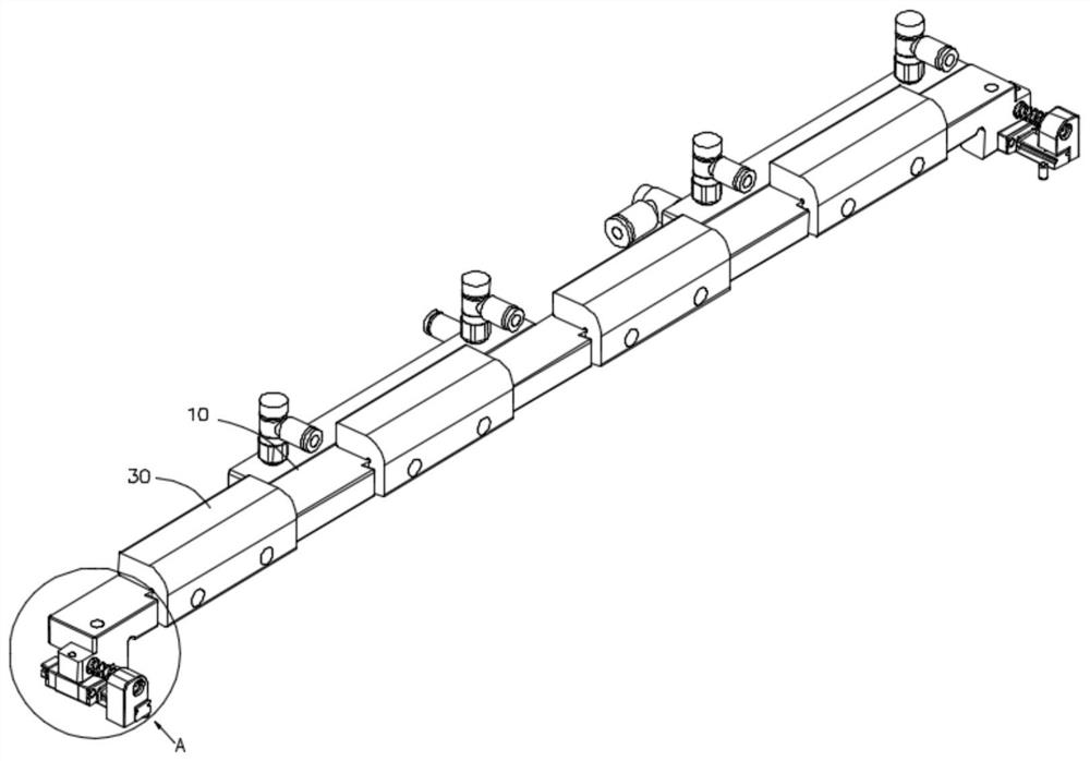
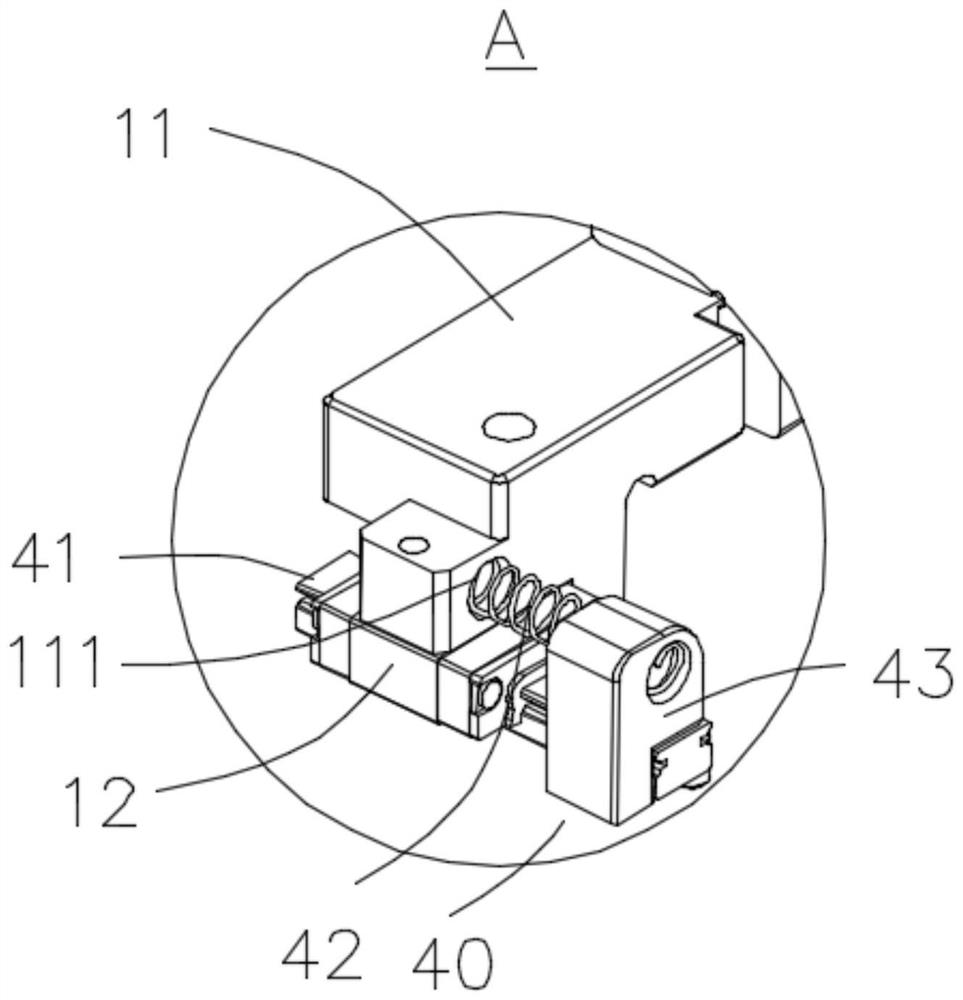
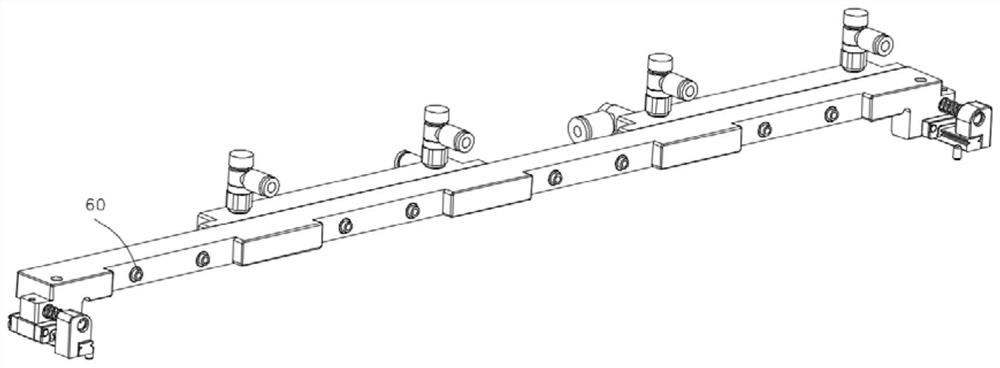
The invention discloses a difference compensation push rod mechanism, which comprises a driving piece, a propelling assembly, at least two difference compensation push blocks and a plurality of elastic pins, wherein the propelling assembly comprises a push plate body, the push plate body is provided with a plurality of push block mounting grooves used for mounting the difference compensation pushblocks, and a plurality of mounting holes used for mounting the elastic pins are formed in the push block mounting grooves; the difference compensation push block is provided with a plurality of elastic pin via holes for mounting elastic pins; one end of the elastic pin is fixed in the mounting hole, the other end of the elastic pin is locked in the via hole through a screw, a to-be-tested productis attached to the difference compensation push block, a difference compensation gap is formed between the difference compensation push block and the push plate body, the driving piece is fixedly connected with the middle of the push plate body and drives the push plate body to move, and the difference compensation push block drives the product to move towards a test interface. Firstly, the propelling assembly is driven by the driving piece to move to slide the to-be-tested product once, and after the to-be-tested product initially reaches the position of the test interface, automatic difference compensation between the test interface and the to-be-tested product is carried out through the elastic effect of the elastic pin.

Description

technical field [0001] The invention relates to the field of testing, in particular to a differential push rod mechanism. Background technique [0002] At present, with the continuous development of high technology, related test fixtures for electronic products are gradually promoted and expanded. Before leaving the factory, it is necessary to carry out board testing for electronic equipment modules such as mobile phones, computers, tablets, and game consoles. It is necessary to perform a plug-in test on the test connector of the test tool and the product to be tested. [0003] However, there are the following defects in the related propulsion device in the test of existing electronic products: [0004] In the prior art, in the testing process of electronic products, simultaneous positioning of multiple products cannot be realized. Generally, a single push plate is used to push the product to the test interface, which cannot compensate for the interface size error caused by...

Claims


Application Information

Patent Timeline
IPC IPC(8): G01R1/02G01R1/04
CPCG01R1/02G01R1/0408
Inventor 黄锦亮
Owner SUZHOU INTELLIGENT AUTOMATION EQUIP CO LTD
Learn More