Shockproof new energy automobile battery fixing device

A new energy vehicle, battery fixing technology, applied in electric power devices, secondary batteries, power devices, etc., can solve problems such as affecting work efficiency, easy battery fall off, easy heat generation during battery use time, etc., to avoid excessive temperature, Less bumpy effect

Inactive Publication Date: 2021-01-26
广州粤丰汽车服务有限公司
View PDF0 Cites 14 Cited by
  • Summary
  • Abstract
  • Description
  • Claims
  • Application Information

AI Technical Summary

Problems solved by technology

At present, most new energy vehicles install batteries with bolts. When the new energy vehicle is jolted for a long time, the bolts will loosen and the battery will easily fall off, which will affect subsequent use. Moreover, if the battery is used for a long time, it will easily heat up and affect work efficiency.

Method used


Image

  • Shockproof new energy automobile battery fixing device
  • Shockproof new energy automobile battery fixing device
  • Shockproof new energy automobile battery fixing device

Examples


Embodiment 1

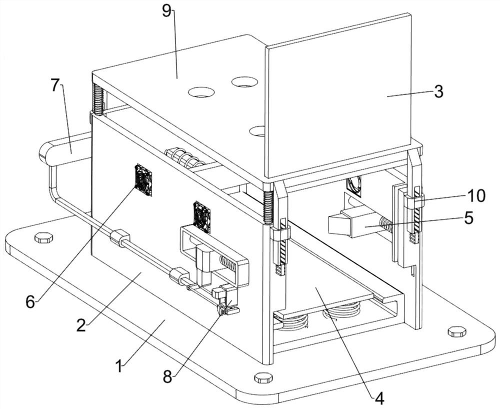
[0027] A shockproof new energy vehicle battery fixing device, such as Figure 1-Figure 3 As shown, it includes a base 1, an outer frame 2, a side plate 3, a bottom shock absorbing mechanism 4 and a clamping mechanism 5. The outer frame 2 is fixedly connected to the top of the base 1, and the left and right sides of the outer frame 2 are slidingly arranged at the front. The side plate 3 is provided with a bottom damping mechanism 4 on the base 1 , and the outer frame 2 is provided with a clamping mechanism 5 .

[0028] The bottom damping mechanism 4 includes a limiting plate 41, a first spring 42 and a first shock absorbing plate 43. The limiting plate 41 is fixedly connected to the top of the base 1, and the limiting plate 41 is located in the outer frame 2. The inner top of the limiting plate 41 is uniform First springs 42 are fixedly connected at intervals, and first damping plates 43 are fixedly connected between tail ends of the first springs 42 .

[0029] The clamping me...

Embodiment 2

[0034] On the basis of Example 1, such as figure 1 , Figure 4 and Figure 5 As shown, a heat dissipation fan 6 is also included, and the left and right sides of the outer frame 2 are symmetrically provided with a heat dissipation fan 6 .

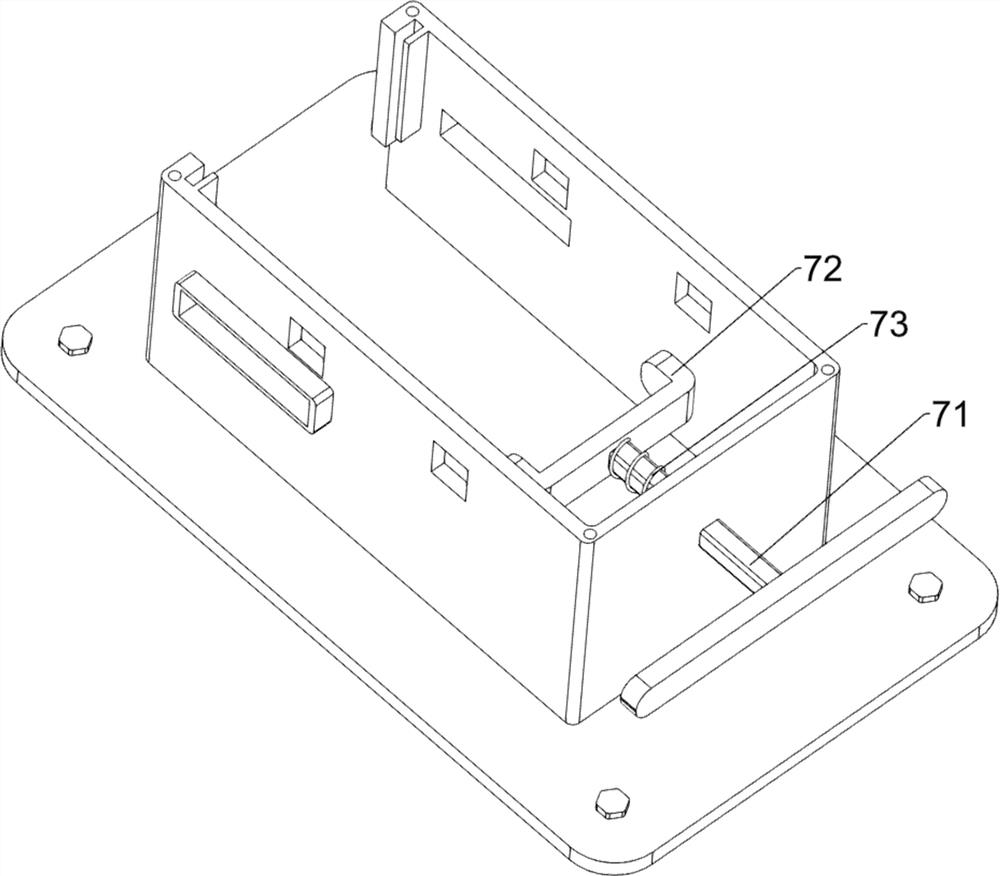
[0035] Also includes a guide mechanism 7, the guide mechanism 7 includes a first connecting rod 71, a first block 72 and a fourth spring 73, the outer frame 2 is provided with a first connecting rod 71 sliding in the middle of the rear side, and the first connecting rod 71 A first block 72 is fixedly connected to the front end, and a fourth spring 73 is fixedly connected between the middle part of the rear side of the first block 72 and the middle part of the inner rear side of the outer frame 2 , and the fourth spring 73 is sleeved on the first connecting rod 71 .

[0036]Also include control mechanism 8, control mechanism 8 includes first guide block 81, second connecting rod 82, third connecting rod 83, second wedge block 84, guide fra...

Embodiment 3

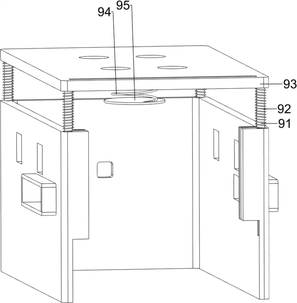
[0041] On the basis of embodiment 1 and embodiment 2, such as figure 1 , Figure 6 and Figure 7 As shown, it also includes a top damping mechanism 9, the top damping mechanism 9 includes a third guide rod 91, a sixth spring 92, a top plate 93, a seventh spring 94 and a second shock absorbing plate 95, and the top of the outer frame 2 is uniform The spaced sliding type is provided with four third guide rods 91, a top plate 93 is fixedly connected between the tops of the four third guide rods 91, and four sixth springs are fixedly connected between the bottom of the top plate 93 and the top of the outer frame 2 at even intervals. 92 , the sixth spring 92 is sleeved on the third guide rod 91 , the seventh spring 94 is affixed in the middle of the bottom of the top plate 93 , and the second damping plate 95 is affixed to the tail end of the seventh spring 94 .

[0042] Also includes a locking mechanism 10, the locking mechanism 10 includes a second guide block 101, a rack bar 1...


PUM


Abstract

The invention relates to a fixing device, in particular to a shockproof new energy automobile battery fixing device. The objective of the invention is to provide the shockproof new energy automobile battery fixing device which can effectively fix a battery and prevent bumping, and has a heat dissipation effect. The shockproof new energy automobile battery fixing device comprises a base, wherein anouter frame is installed on one side of the base; a side plate which is mounted on the outer frame in a sliding manner; and a bottom damping mechanism which is mounted on the base and used for damping and limiting the bottom of the battery. The side plates are pulled to move upwards to be separated from the outer frame, then the bottom damping mechanism is pressed to move downwards, the clampingmechanism is pulled to operate, then the battery is placed in the bottom damping mechanism, and when the battery is placed at a proper position, the clamping mechanism is loosened, and then the bottomdamping mechanism and the clamping mechanism limit the battery. And the battery of the new energy automobile can be effectively fixed and is not easy to bump.

Description

technical field [0001] The invention relates to a fixing device, in particular to a shockproof new energy vehicle battery fixing device. Background technique [0002] New energy vehicles refer to vehicles that use unconventional vehicle fuels as power sources, integrate advanced technologies in vehicle power control and drive, and form vehicles with advanced technical principles, new technologies, and new structures. Most new energy vehicles are powered by batteries. At present, most of the new energy installation batteries are fixed by bolts. When the new energy vehicles are bumped for a long time, the bolts will loosen, and the battery will easily fall off, which will affect the subsequent use, and the battery will heat up if it is used for a long time, which will affect the work efficiency. [0003] Therefore urgently need to research and develop a kind of can effectively fix battery, prevent bump, and have the anti-vibration new energy vehicle battery fixing device of c...

Claims


Application Information

Patent Timeline
Patent Type & Authority Applications(China)
IPC IPC(8): H01M50/242H01M10/052H01M10/613H01M10/625H01M10/6563B60K1/04
CPCB60K1/04H01M10/052H01M10/613H01M10/625H01M10/6563Y02E60/10
Inventor 郭茜璐
Owner 广州粤丰汽车服务有限公司
Why Eureka
Try Eureka