Intelligent balancing device for frame body operation

A balancing device and intelligent technology, which is applied in the field of compact racks, can solve the problems of unreasonable structural composition adjustment mode, untimely anti-falling balance effect, and poor balance effect, so as to achieve sensitive adjustment action and reduce or avoid accidents The effect of simple and reasonable structure

Pending Publication Date: 2021-01-29
江西方迪科技有限公司
View PDF0 Cites 0 Cited by
  • Summary
  • Abstract
  • Description
  • Claims
  • Application Information

AI Technical Summary

Problems solved by technology

In view of this situation, most of the existing compact racks are equipped with anti-dumping safety protection devices, and the existing anti-dumping devices are not reasonable due to the structural composition and corresponding adjustment mode, and the anti-dumping balance effect is not timely and the reliability is low. , poor balance

Method used


Image

  • Intelligent balancing device for frame body operation
  • Intelligent balancing device for frame body operation
  • Intelligent balancing device for frame body operation

Examples


Embodiment 2

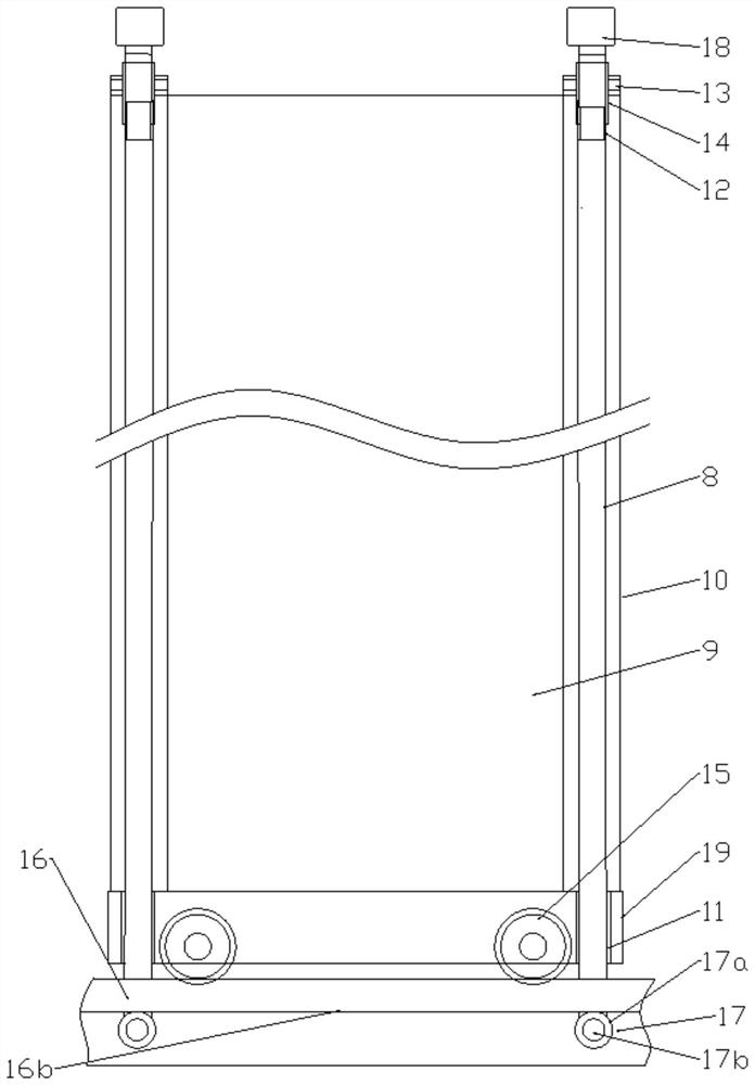
[0019] In embodiment 2, such as Figure 4 As shown, in this example, the kinematic coupling device of the correcting force is a composite multi-function correcting force kinematic coupling device, and its matching balance adapter is a compound matching balancing adapter. The composite multi-functional correction force motion coupling device includes composite rolling or sliding couplers fixedly connected to the lower end of the balance adjustment rod on the left and right sides and the upper and lower walls of the inner or outer side of the track respectively. The two bearing devices of the corresponding upper and lower parts, the bearing 17a of its lower bearing device 17-2 is in rolling connection with the lower wall surface 16b of the protruding part of the track 16, and the bearing 17a of the upper bearing device 17-1 is connected with the upper wall surface of the track. 16a is rollingly connected, and the bearing shaft 17b of the upper and lower bearing devices is fixedl...

Embodiment 3

[0024] In embodiment 3, such as Figure 5 with 6 shown. The balance adjustment rods are respectively set in the inner cavity of the frame-type columns on the left and right sides in the middle of the frame body. The two rails at both ends of the frame body are respectively equipped with a composite multifunctional correction force motion coupling device, and its composite multifunctional correction effect The force motion coupling device also includes a linkage integrated synchronous transmission rod 27, and the two ends of the linkage integrated synchronous transmission rod are respectively fixedly connected to the bearing shaft 17b or the sliding shaft of the rolling or sliding coupler of the two tracks of the compact shelf. The bearing 17a or sliding body of its rolling or sliding coupler is respectively rolling or slidingly connected to the upper wall surface 16a of the track of the frame body and the lower wall surface 16b of the protrusion on one side of the track. The...

Embodiment 4

[0025] In embodiment 4, such as Figure 7 shown. The two tracks corresponding to the two ends of the frame body 9 are respectively provided with balance adjustment rods corresponding to each other on the left and right sides, and the two pairs of left and right balance adjustment rods at the two ends of the frame body are respectively arranged in the corresponding two sides of the column near the track, or next to the column. The outer part of the frame. The similar balance adapter of the balance adjustment rod is connected with the balance motor through a bridge-type co-balance correction driving device. The bridge-type co-balance correction transmission device includes a balance drive main shaft 25 arranged in the longitudinal middle of the top wall of the frame body, which is respectively connected to the balance drive main shaft at both ends of the balance drive main shaft through a plane 90-degree direction-changing bevel gear transmission 20a and the balance drive main ...


PUM


Abstract

The invention discloses an intelligent balancing device for frame body operation. The device comprises a tilt angle sensor and a balance adjustment controller, and the balance adjustment controller comprises a reference comparison direction recognizer, a horizontal reference setter, a start control setter and a balance corrector connected to the reference comparison direction recognizer. The output ends of the tilt angle sensor and the horizontal reference setter and the input end of the balance corrector are respectively connected with the input end and the output end of the reference comparison direction recognizer, and the output end of the start control setter is connected to the input end of the balance corrector. The intelligent balancing device for frame body operation is timely, stable and reliable in balance adjustment and good in protection effect.

Description

technical field [0001] The invention relates to a compact shelf. In particular, it relates to an intelligent balancing device for rack body operation. Background technique [0002] With the improvement of its automation control degree and concentration, the requirements for the use safety of compact racks are getting higher and higher. Due to its narrow, long and high shape, there must be a phenomenon of swinging on both sides during operation, and the current compact rack has the characteristics of quick start and high-speed operation, which increases the tilting of the rack body due to its swing during operation. possible. In view of this situation, most of the existing compact racks are equipped with anti-dumping safety protection devices, and the existing anti-dumping devices are not reasonable due to the structural composition and corresponding adjustment mode, and the anti-dumping balance effect is not timely and the reliability is low. , the balance effect is poor....

Claims


Application Information

Patent Timeline
Patent Type & Authority Applications(China)
IPC IPC(8): A47B53/02A47B87/00A47B91/06A47B97/00
CPCA47B53/02A47B87/00A47B91/066A47B97/00A47B2097/008
Inventor 赵宾雷聂斌华
Owner 江西方迪科技有限公司
Why Eureka
Try Eureka