Check patentability & draft patents in minutes with Patsnap Eureka AI!

A kind of shot blasting equipment

A technology of equipment and shot blasting chamber, which is applied in the field of automobile parts processing equipment, can solve problems such as low workpiece processing efficiency, and achieve the effect of improving processing efficiency

Active Publication Date: 2022-02-15
ZHEJIANG JIULONG MACHINERY
View PDF9 Cites 0 Cited by
  • Summary
  • Abstract
  • Description
  • Claims
  • Application Information

AI Technical Summary

Problems solved by technology

[0004] In view of the related technologies mentioned above, the inventor believes that the existing shot blasting equipment has the defect of relatively low processing efficiency of workpieces

Method used


Image

  • A kind of shot blasting equipment
  • A kind of shot blasting equipment
  • A kind of shot blasting equipment

Examples


Embodiment Construction

[0034] The following is attached Figure 1-7 The application is described in further detail.

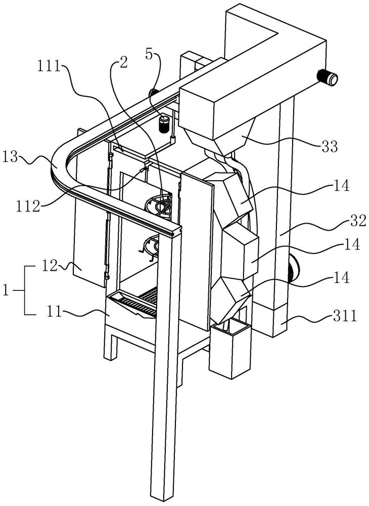
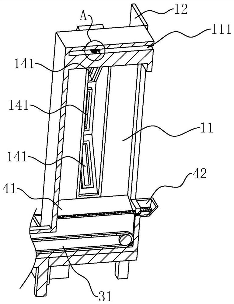
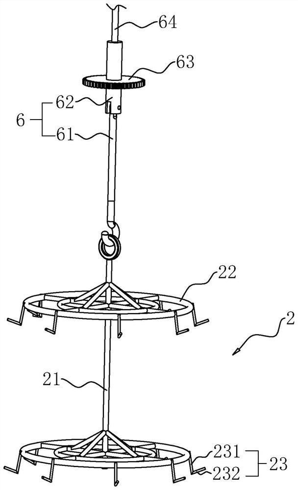
[0035] The embodiment of the present application discloses a kind of shot blasting equipment, referring to figure 1 and figure 2 , comprising a shot blasting chamber 1 and a multi-workpiece suspension device, the shot blasting chamber 1 includes a chamber body 11 and a door body 12 hinged with the chamber body 11, the shot blasting chamber 1 is provided with a blasting device 14, and the number of blasting devices 14 There are three and arranged vertically, the throwing outlet 141 of the shot blasting device 14 in the middle is arranged horizontally, the throwing port 141 of the blasting device 14 above is inclined downward, and the blasting device 14 below is positioned at the throwing port 141. The outlet 141 is inclined upwards. The multi-workpiece suspension device includes a suspension frame 2 and a driving member 5 for driving the suspension frame 2 to rotate. The suspension...


PUM


Abstract

The application relates to a shot blasting equipment, which includes a shot blasting chamber and a multi-workpiece suspension device. The shot blasting chamber is provided with a shot blaster. The multi-workpiece suspension device includes a suspension frame and a driving member for driving the suspension frame to rotate. The suspension frame is located in the shot blasting chamber, and the driving member is arranged on the shot blasting chamber. This application has the effect of improving the processing efficiency of workpieces.

Description

technical field [0001] The present application relates to the field of auto parts processing equipment, in particular to a shot blasting equipment. Background technique [0002] The cylinder head of the engine is cast aluminum. In order to enhance the performance of the engine cylinder head, it is usually necessary to perform shot blasting on the cylinder head of the engine. [0003] Shot blasting refers to the use of high-speed rotating impellers to throw shot blasting materials such as steel sand from the shot blaster to the surface of the cylinder head of the engine to clean the surface of the cylinder head of the engine and achieve the purpose of improving the surface strength at the same time. [0004] In view of the related technologies mentioned above, the inventor believes that the existing shot blasting equipment has the defect of relatively low processing efficiency for workpieces. Contents of the invention [0005] In order to improve the processing efficiency ...

Claims


Application Information

Patent Timeline
Patent Type & Authority Patents(China)
IPC IPC(8): B24C9/00
CPCB24C9/00
Inventor 叶艺龙胡郑州陈军方兵
Owner ZHEJIANG JIULONG MACHINERY
Features
  • R&D
  • Intellectual Property
  • Life Sciences
  • Materials
  • Tech Scout
  • Unparalleled Data Quality
  • Higher Quality Content
  • 60% Fewer Hallucinations
Learn More