
Optical cable based on high flame retardance and high light transmittance

A technology with high light transmittance and high flame retardancy, applied in the field of optical cables, it can solve the problems of damage or wear at the bending position, poor impact resistance, and easy damage to internal wires.

Inactive Publication Date: 2021-01-29
芜湖腾飞信息科技有限公司
View PDF1 Cites 0 Cited by
  • Summary
  • Abstract
  • Description
  • Claims
  • Application Information

AI Technical Summary

Problems solved by technology

[0005] In order to solve the above technical problems, the present invention provides an optical cable based on high flame retardant and high light transmittance to solve the problem that the existing high flame retardant high light transmittance optical cable has poor internal support structure and low impact resistance when it is in use. Poor, and when encountering impact or inserting sharp objects, it is easy to damage its internal wires, and when the existing high flame-retardant and high-transmittance optical cables are used, the bending position of the optical cable cannot be protected, and after long-term use, the bending The position is vulnerable to damage or wear, and cannot be easily fixed at an appropriate height when in use

Method used


Image

  • Optical cable based on high flame retardance and high light transmittance
  • Optical cable based on high flame retardance and high light transmittance
  • Optical cable based on high flame retardance and high light transmittance

Examples


Embodiment

[0034] as attached figure 1 to the attached Figure 8 shown:

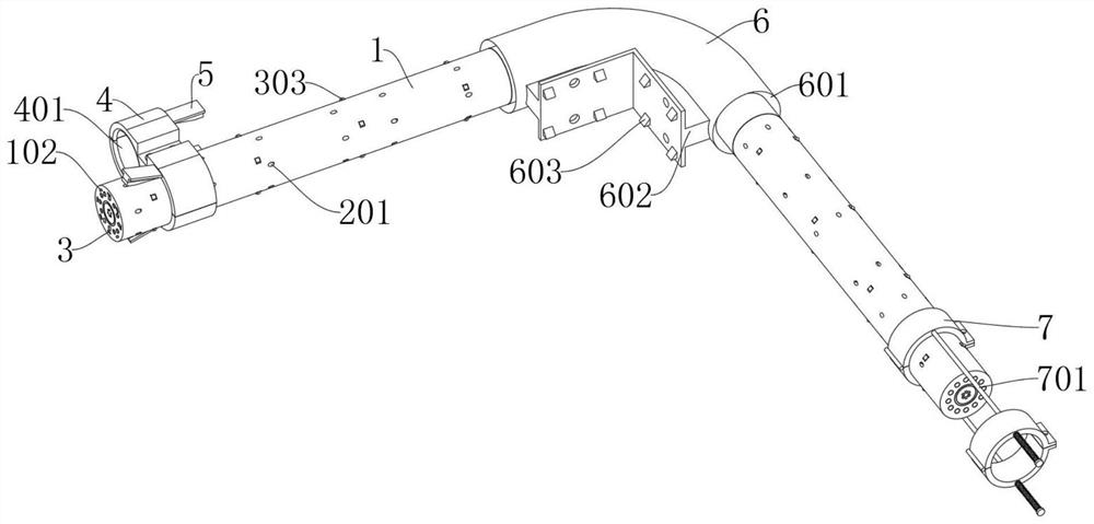
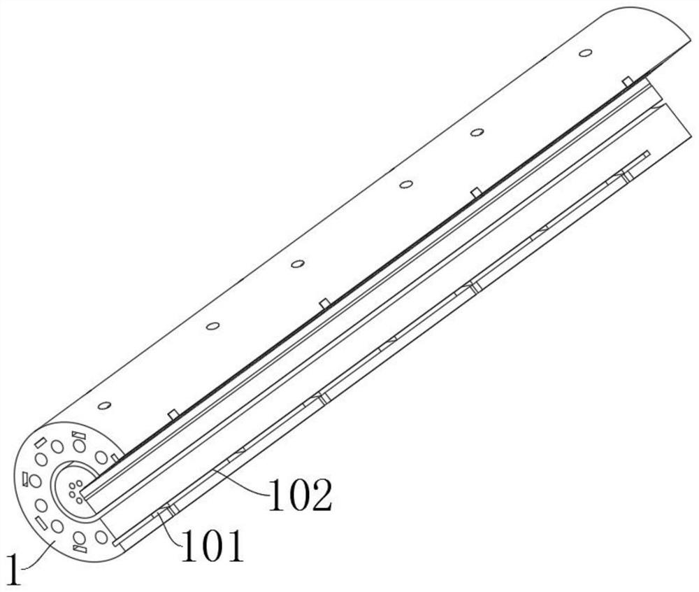
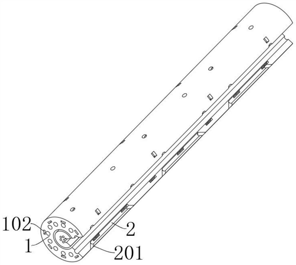
[0035] The present invention provides an optical cable based on high flame retardancy and high light transmittance, comprising a main body 1, a heat dissipation groove 2, a support member 3, a connecting head 4, a top block 5, a protective member 6 and a connecting ring 7; the main body 1 is the optical cable body, and The inside of the main body 1 is fixedly installed with wires; the heat dissipation groove 2 is arranged on the outside of the main body 1, and the heat dissipation grooves 2 are arranged in a ring; The inner end of the top block 5 is installed in the interior of the fixing groove 401 by embedding, and the rectangular block at the rear end of the top block 5 is embedded and installed in the limiting grooves on both sides of the guide groove 402; The outside of the main body 1 and the inside of the connecting ring 7 is fixedly connected to the outside of the main body 1 .

[0036] The supporting memb...


PUM


Abstract

The invention provides an optical cable based on high flame retardance and high light transmittance, relates to the technical field of optical cables, and aims at solving the problems that when an existing optical cable with high flame retardance and high light transmittance is used, an internal supporting structure of the optical cable is poor, the impact resistance is poor, and when impact or the insertion of sharp objects occurs, internal wires of the optical cable are prone to damage. The optical cable comprises a main body, heat dissipation grooves and supporting pieces. The main body isan optical cable body, and the interior of the main body is fixedly equipped with a wire. And the heat dissipation grooves are formed in the outer side of the main body and are annularly arranged. Thesupporting pieces are installed in the main body, so that the supporting pieces can effectively support the main body, when the main body encounters impact, the supporting pieces and a connecting piece can be matched together to buffer the impact force, and the situation that the main body and an internal wire are damaged due to the impact force is avoided; when a sharp object penetrates, the sharp object can also be in contact with the supporting pieces, so that the sharp object can be effectively fixed by the supporting pieces and a gap between the supporting pieces.

Description

technical field [0001] The invention belongs to the technical field of optical cables, and more particularly, particularly relates to optical cables based on high flame retardancy and high light transmittance. Background technique [0002] Fiber optic cables are manufactured to meet optical, mechanical, or environmental performance specifications, and are telecommunication cable assemblies that utilize one or more optical fibers in a sheathing as the transmission medium and can be used individually or in groups. [0003] For example, the application number: CN201811069864.3 relates to a high-light-transmitting flame-retardant optical cable, comprising a steel-plastic layer, the inner side of the steel-plastic layer is wrapped with a fire-proof composite layer, and the outer side of the steel-plastic layer is fixedly connected with a support block, The inner side of the fireproof composite layer is wrapped with a metal layer, the inner side of the metal layer is provided with...

Claims


Application Information

Patent Timeline
IPC IPC(8): G02B6/44
CPCG02B6/4429G02B6/4436
Inventor 王和
Owner 芜湖腾飞信息科技有限公司
Learn More