Supercharge Your Innovation With Domain-Expert AI Agents!

Antenna array

一种天线阵列、天线元件的技术,应用在天线阵列、天线、单独通电的天线阵列等方向,能够解决缩短传统天线阵列100通信距离等问题

Pending Publication Date: 2021-01-29
DELTA ELECTRONICS INC
View PDF3 Cites 1 Cited by
  • Summary
  • Abstract
  • Description
  • Claims
  • Application Information

AI Technical Summary

Problems solved by technology

Although the aforementioned non-uniform distribution of output power can improve the side beam suppression ratio, it also shortens the communication distance of the traditional antenna array 100 at the same time

Method used


Image

  • Antenna array
  • Antenna array
  • Antenna array

Examples


Embodiment Construction

[0066] In order to make the purpose, features and advantages of the present invention more comprehensible, the specific embodiments of the present invention are listed below, together with the accompanying drawings, and are described in detail as follows.

[0067] Certain terms are used in the specification and related application documents to refer to particular elements. Those skilled in the art should understand that hardware manufacturers may use different terms to refer to the same component. This description and related application documents do not use the difference in name as a way to distinguish components, but use the difference in function of components as a criterion for distinguishing. The words "comprising" and "comprising" mentioned throughout the specification and related application documents are open-ended terms, so they should be interpreted as "including but not limited to". The term "approximately" means that within an acceptable error range, those skille...


PUM


Abstract

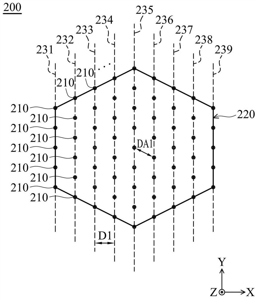
The invention provides an antenna array which comprises a plurality of antenna elements arranged on a plane, the antenna elements are arranged to form a symmetrical pattern, and the symmetrical pattern is not a square or a rectangle. The antenna elements have the same output power. A radiation pattern of the antenna array includes a main beam and a side beam, and the main beam is at least 18 dB higher than the side beam.

Description

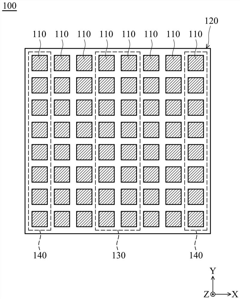
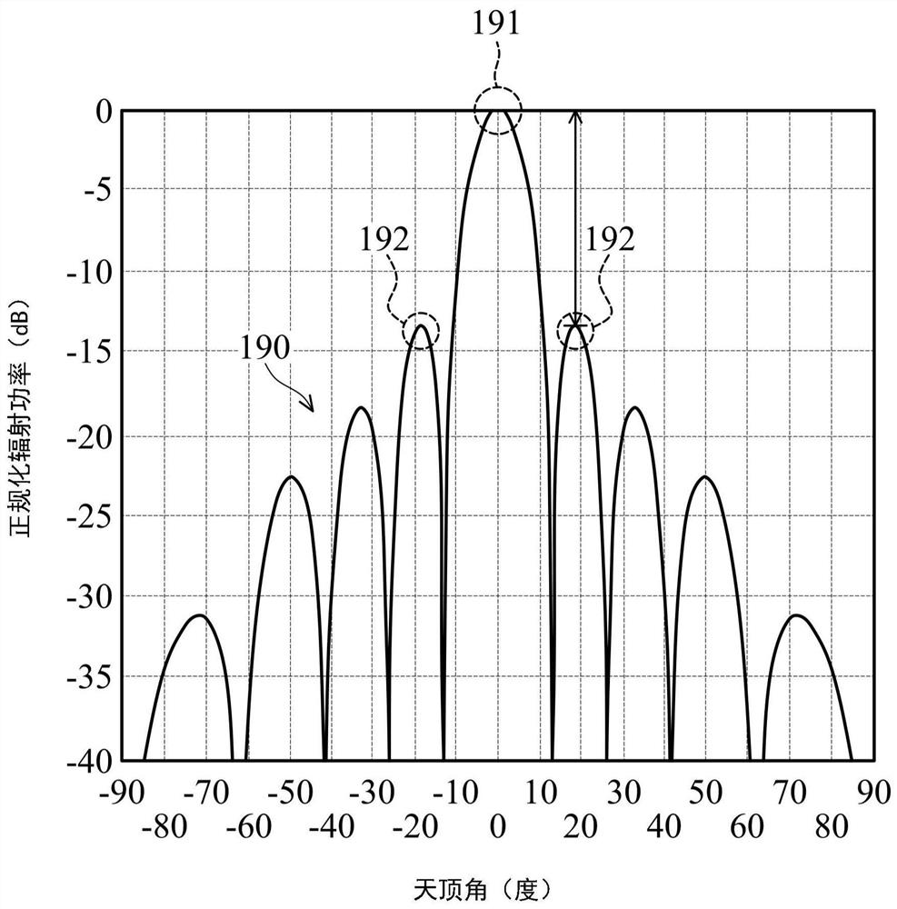
technical field [0001] The invention relates to an antenna array (Antenna Array), in particular to an antenna array capable of suppressing side beams (Sidelobe) and improving communication distance (Communication Distance). Background technique [0002] Figure 1A A top view of a conventional antenna array 100 is shown. Such as Figure 1A As shown, the conventional antenna array 100 includes a plurality of antenna elements (Antenna Elements) 110 , wherein the antenna elements 110 are arranged into a square (or a rectangle) 120 . [0003] Figure 1B A schematic diagram showing a radiation pattern (Radiation Pattern) 190 of the conventional antenna array 100 , wherein the horizontal axis represents the zenith angle (Theta), and the vertical axis represents the normalized radiation power (Normalized Radiation Power). Such as Figure 1B As shown, the radiation pattern 190 of the antenna array 100 includes a main beam (Main Lobe) 191 and a side beam 192, and the main beam 191 ...

Claims


Application Information

Patent Timeline
Patent Type & Authority Applications(China)
IPC IPC(8): H01Q21/29H01Q21/06
CPCH01Q21/293H01Q21/061H01Q21/20H01Q3/26H01Q1/246H01Q21/0025H01Q21/28H01Q1/523
Inventor 黄杰超陈彦廷
Owner DELTA ELECTRONICS INC
Features
  • R&D
  • Intellectual Property
  • Life Sciences
  • Materials
  • Tech Scout
  • Unparalleled Data Quality
  • Higher Quality Content
  • 60% Fewer Hallucinations
Learn More