Hidden new energy automobile charging pile

A technology for new energy vehicles and charging piles, applied in electric vehicle charging technology, charging stations, electric vehicles, etc., can solve problems such as inability to realize convenient functions, damage to charging piles, economic losses, etc., to reduce the possibility of moisture exposure, Longer service life and flexible use

Inactive Publication Date: 2021-02-02
东营瑞尔泰机电科技有限公司
View PDF5 Cites 0 Cited by
  • Summary
  • Abstract
  • Description
  • Claims
  • Application Information

AI Technical Summary

Problems solved by technology

[0003] At present, whether it is a community or a public building, there are very few places where charging piles can be installed. The social environment limits the popularity of charging piles. The current charging piles are basically installed on the ground or walls, but they take up a lot of space. , and simply placing the charging pile outdoors is easy to cause damage to the charging pile due to human or environmental factors, which not only fails to realize the function of convenience, but also causes economic losses. Therefore, in view of the above status quo, it is urgent to develop a hidden new energy Car charging piles to overcome the deficiencies in current practical applications

Method used


Image

  • Hidden new energy automobile charging pile
  • Hidden new energy automobile charging pile
  • Hidden new energy automobile charging pile

Examples


Embodiment 1

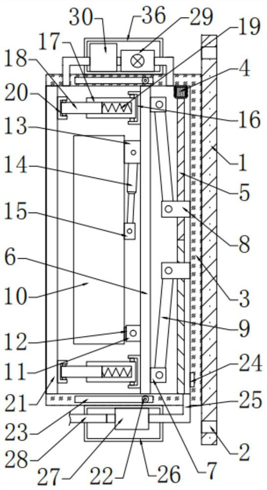
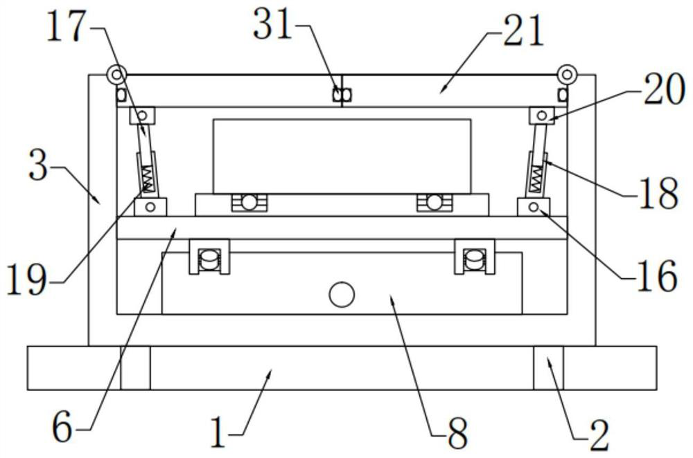
[0027] see Figure 1-4 , in an embodiment of the present invention, a hidden new energy vehicle charging pile, including a mounting plate 1, the left side of the mounting plate 1 is fixedly connected with a storage box 3, and the inner side of the storage box 3 is slidingly connected with a movable plate 6 , the right end of the movable plate 6 is connected to the storage box 3 through a telescopic mechanism, the left side of the movable plate 6 is provided with a charging pile 10, and a supporting mechanism is provided between the charging pile 10 and the movable plate 6, and the placing The left side of the box 3 is hingedly provided with a box door 21, and the box door 21 is connected with the movable plate 6 through a transmission mechanism.

Embodiment 2

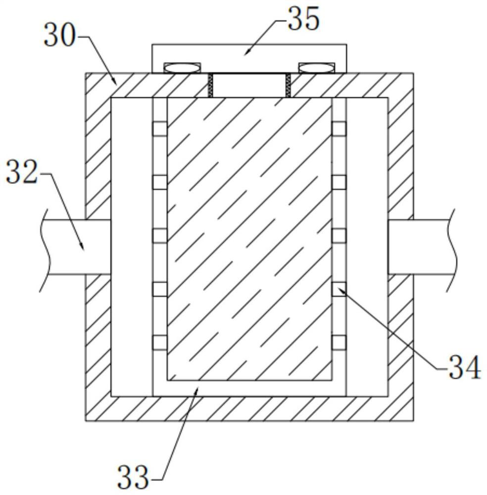
[0029] In this embodiment, the telescopic mechanism includes a motor 4 that is bolted to the inside of the storage box 3, the output end of the lower side of the motor 4 is connected to the threaded rod 5, and the outer sides of the upper and lower ends of the threaded rod 5 are threaded. Movable block 8, described movable block 8 is hingedly provided with connecting rod 9 near the side of movable plate 6, and the other ends of described connecting rod 9 on the upper and lower sides are respectively fixedly connected with the first connecting block arranged at the upper and lower ends on the right side of movable plate 6 7 hinged, by setting a telescopic mechanism, using the motor 4 to drive the threaded rod 5 to rotate, the threaded rod 5 drives the movable blocks 8 on both sides to move, and the movable block 8 can realize the expansion and contraction of the movable plate 6 through the connecting rod 9, thereby realizing the charging pile. The retraction of 10 solves the pro...


PUM


Abstract

The invention relates to the technical field of new energy automobile charging piles, in particular to a hidden new energy automobile charging pile which comprises a mounting plate, a placement box fixedly connected to the left side of the mounting plate, a movable plate slidably connected to the inner side of the placement box, a telescopic mechanism connected between the right end of the movableplate and the placement box, a charging pile is arranged on the left side of the movable plate, a support mechanism is arranged between the charging pile and the movable plate, a box door is arrangedon the left side of the placement box in a hinge mode, and the box door is connected to the movable plate through a transmission mechanism. The telescopic mechanism is arranged, so that the chargingpile can be retracted and released, and the problem of large occupied area of an existing charging pile is solved; the risk that the charging pile is damaged by human factors or environmental factorsis reduced, by arranging the support mechanism, the charging pile can rotate through stretching and retracting of the telescopic rod, and therefore the charging pile can be fixed to a wall and can also be buried underground.

Description

technical field [0001] The invention relates to the technical field of new energy vehicle charging piles, in particular to a hidden new energy vehicle charging pile. Background technique [0002] New energy vehicles refer to the use of unconventional vehicle fuels as power sources (or the use of conventional vehicle fuels and new vehicle power devices), and the comprehensive vehicle power control and advanced technology in driving, the formation of advanced technical principles, with Automobiles with new technology and new structure. The battery life of new energy vehicles is inseparable from charging piles. The function of charging piles is similar to that of fuel dispensers in gas stations. They can be fixed on the ground or walls, installed in public buildings and residential parking lots or charging stations, and can be charged according to different voltage levels. To charge various types of electric vehicles, the input end of the charging pile is directly connected to...

Claims


Application Information

Patent Timeline
Patent Type & Authority Applications(China)
IPC IPC(8): B60L53/31B60L53/30F26B21/08
CPCB60L53/31B60L53/30F26B21/08Y02T10/70Y02T10/7072Y02T90/12
Inventor 杨又伦曹剑覃远福刘建华
Owner 东营瑞尔泰机电科技有限公司
Why Eureka
Try Eureka