Forming device

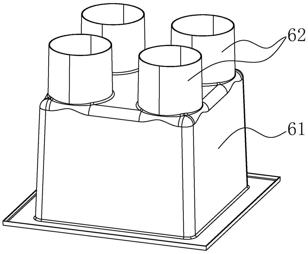
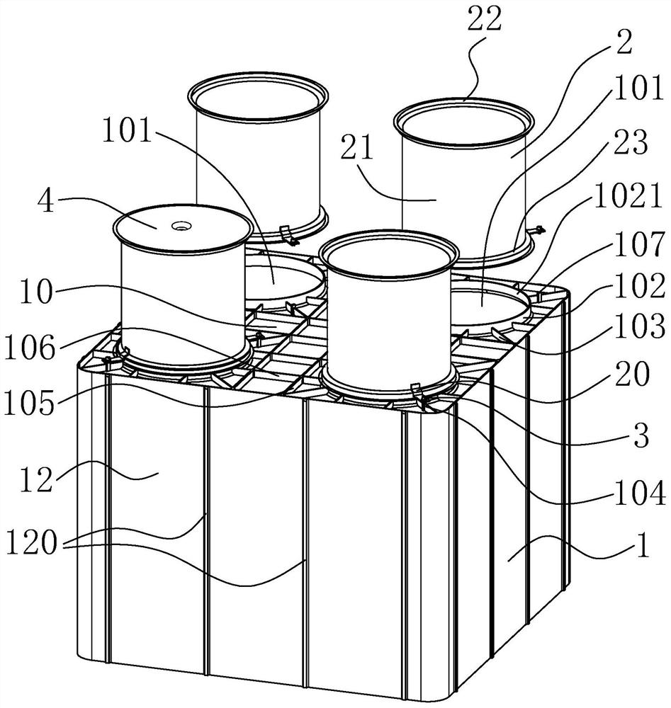
A forming device and barrel-shaped technology, which is applied in the field preparation of formwork/formwork/work frame, building components, construction, etc., can solve the problem of inability to adjust the circular barrel 62, damage the integrity of the reserved holes, and limited structural strength and other issues, to achieve a more stable and even support effect, to facilitate transportation and handling, and to reduce difficulty

Pending Publication Date: 2021-02-02
ベロテクノロジーズドンタイカンパニーリミテッド
View PDF0 Cites 0 Cited by
  • Summary
  • Abstract
  • Description
  • Claims
  • Application Information

AI Technical Summary

Problems solved by technology

Due to the limited structural strength of this kind of forming mold, it is easily deformed when it is squeezed during concrete grouting, which destroys the integrity of the reserved hole
Moreover, since the number of round barrels 62 on the square barrel 61 is fixed, it is impossible to arbitrarily adjust the number of round barrels 62 or the position on the square barrel 61 as required by the project.

Method used


Image

  • Forming device
  • Forming device
  • Forming device

Examples


Embodiment Construction

[0037] Specific structural and functional details disclosed herein are merely representative and for purposes of describing exemplary embodiments of the present invention. However, the present invention may be embodied in many alternative forms and should not be construed as limited only to the embodiments set forth herein.

[0038] In the description of the present invention, it should be understood that the terms "center", "lateral", "top", "bottom", "left", "right", "vertical", "horizontal", "top", " The orientation or positional relationship indicated by "bottom", "inside", "outside", etc. is based on the orientation or positional relationship shown in the accompanying drawings, and is only for the convenience of describing the present invention and simplifying the description, rather than indicating or implying the indicated device or The components must have a particular orientation, or be constructed and operated in a particular orientation, and therefore should not be ...


PUM


Abstract

The invention discloses a forming device which is used for reserving a hole in a floor. The forming device comprises a barrel-shaped structure, a tubular structure and a locking piece. The barrel-shaped structure comprises a top plate and a barrel wall which is connected to the periphery of the top plate in a surrounding mode and extends downwards, and the top plate is provided with at least one hole; the at least one tubular structure corresponds to the at least one hole and can be arranged on the top plate of the barrel-shaped structure to communicate with the hole; and the locking piece isused for locking the at least one tubular structure on the top plate of the barrel-shaped structure.

Description

technical field [0001] The invention relates to a molding device, in particular to a molding device used for preserving holes in floor boards. Background technique [0002] In the construction of cement buildings, it is necessary to reserve holes on the floor of the floor to provide air circulation or passages for subsequent erection of pipelines. In a typical construction method, after the building formwork is erected, the forming mold is erected at the predetermined position on the formwork, and then the concrete grouting operation is performed, and the concrete is laid on the formwork and the outer surface of the forming mold. After the concrete has set, the desired openings can be created between the resulting floor slabs. [0003] figure 1 Shown is the currently used molding die, which is made of sheet molding compound (SMC), including an integrally formed square barrel 61 and several round barrels 62 . As shown in the figure, the circular barrel 62 communicates with...

Claims


Application Information

Patent Timeline
IPC IPC(8): E04G15/06
CPCE04G15/06E04G15/063
Inventor 黄建德
Owner ベロテクノロジーズドンタイカンパニーリミテッド
Why Eureka
Try Eureka