Optical field display system based on optical waveguide coupled light exit pupil segmentation-combination control

A combined control and display system technology, applied in the direction of instruments, etc., can solve the problems of not having a light and thin structure

Active Publication Date: 2021-02-02
驻景(广州)科技有限公司
View PDF9 Cites 6 Cited by
  • Summary
  • Abstract
  • Description
  • Claims
  • Application Information

AI Technical Summary

Problems solved by technology

However, the display system described in the above-mentioned patent either requires an external traditional large-size flat display screen, or zo

Method used


Image

  • Optical field display system based on optical waveguide coupled light exit pupil segmentation-combination control
  • Optical field display system based on optical waveguide coupled light exit pupil segmentation-combination control
  • Optical field display system based on optical waveguide coupled light exit pupil segmentation-combination control

Examples


Embodiment Construction

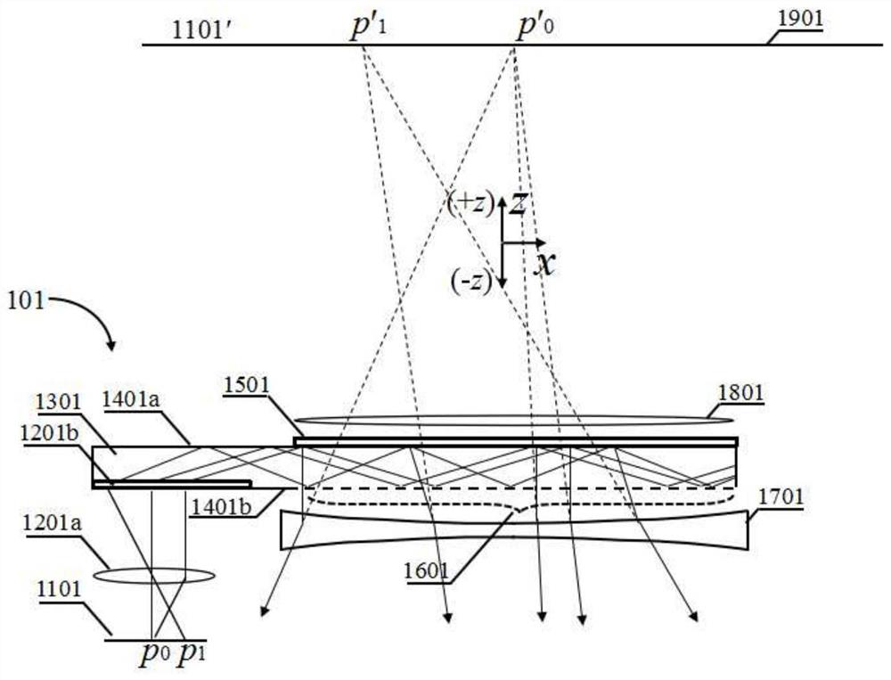
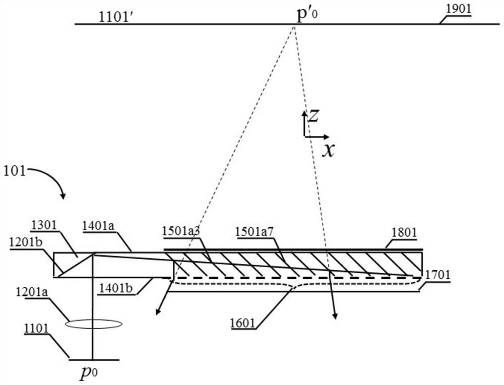
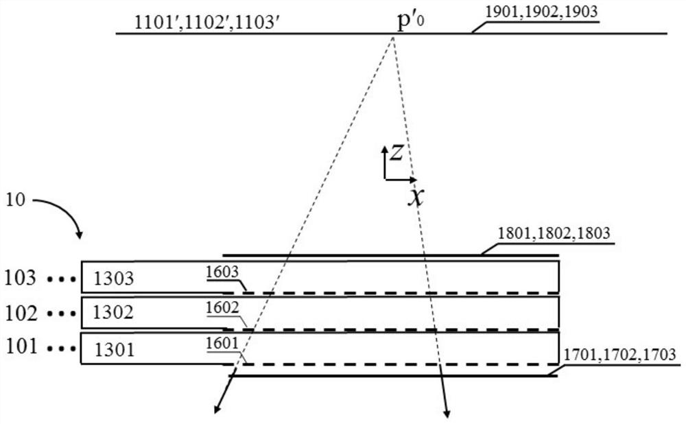
[0093] The display system of the present invention uses the optical waveguide projection unit stack structure as the optical information transmission and projection structure, through the division-combination control of each optical waveguide projection unit coupling out the light exit pupil, combined with the polarization characteristics or / and timing characteristics, by each light The waveguide projection unit projects corresponding views whose viewpoint distance is smaller than the diameter of the observer's pupil to each eye of the observer through different outcoupling light exit pupils or different areas of different outcoupling light exit pupils. A light field three-dimensional display system with a light and thin optical structure is built based on the stacked film-shaped optical waveguide by using the spatial superposition of light emitted from different views received by each eye. Compared with the monocular multi-view light field display system disclosed in PCT15 / 481...


PUM


Abstract

The invention discloses an optical field display system based on optical waveguide coupled light exit pupil segmentation-combination control. The system takes at least one optical waveguide projectionunit for projecting an image to a limited far projection surface as a display unit, and performs region segmentation combination control of the coupled light exit pupil through the at least one optical waveguide projection unit, In combination with polarization characteristics or/and time sequence characteristics, views with the viewpoint distance smaller than the pupil diameter of an observer are projected to each eye of the observer, spatial superposition of light beams from more than one view is used for forming monocular spatial light spot distribution capable of being naturally focused,and three-dimensional light field display is achieved. By means of the optical waveguide, the display system has a light and thin structure and can be applied to various screens and portable display terminals such as head-mounted VR, AR, mobile phones and iPads.

Description

technical field [0001] The present invention relates to three-dimensional display, and more specifically relates to a light field display system based on optical waveguide outcoupling light exit pupil division-combination control. Background technique [0002] Optical waveguide is a commonly used optical structure in the field of three-dimensional display due to its light and thin structural volume. Especially in the field of augmented reality (AR), thin and light 3D glasses based on optical waveguide structures are being used more and more widely. However, the existing optical waveguide 3D display system is still mainly based on stereoscopic technology, only by projecting only one view to the observer's binoculars, and using the convergence of the binocular viewing directions in space to realize the presentation of 3D depth. But in order to clearly see the respective views of the two eyes, the viewer needs to focus his / her eyes on the display surface. The resulting focus-...

Claims


Application Information

Patent Timeline
IPC IPC(8): G02B30/24G02B30/25
Inventor 刘立林滕东东
Owner 驻景(广州)科技有限公司
Why Eureka
Try Eureka