
Near-eye display based on holographic waveguide

A near-eye display, holographic waveguide technology, applied in instruments, optical components, optics, etc., can solve problems such as small field of view, loss of resolution, and inability to provide viewing experience effects, to increase the field of view, reduce size, The effect of improving the viewing experience

Pending Publication Date: 2019-09-24
JURONG FUXIN ELECTRONICS
View PDF1 Cites 11 Cited by
  • Summary
  • Abstract
  • Description
  • Claims
  • Application Information

AI Technical Summary

Problems solved by technology

However, the resolution loss of the display device is relatively serious, and the viewing angle is small, which cannot provide a better viewing experience.

Method used


Image

  • Near-eye display based on holographic waveguide
  • Near-eye display based on holographic waveguide
  • Near-eye display based on holographic waveguide

Examples


Embodiment 1

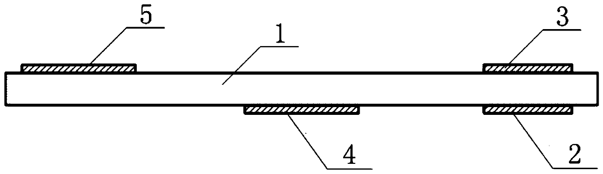
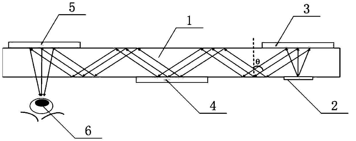
[0031] Such as figure 1 , 2 As shown, this embodiment provides a near-eye display based on a holographic waveguide, including: an optical waveguide 1 and an array light source 2 arranged on both sides of the optical waveguide 1, an in-coupling optical element 3, a reflective spatial light modulator 4, an output Coupling optical element 5; the array light source 2 and the in-coupling optical element 3 are located on the opposite side of the optical waveguide 1; the opposite side of the out-coupling optical element 5 is the human eye 6 viewpoint; the light emitted by the array light source 2 passes through the input After being reflected by the coupling optical element 3, it is irradiated on the reflective spatial light modulator 4 and modulated by the reflective spatial light modulator 4, and then reflected to the outcoupling optical element 5, and the modulated light is guided out by the outcoupling optical element 5 The waveguide 1 enters the human eye 6 ; the reflective spa...

Embodiment 2

[0047] Such as Figures 5 to 7 As shown, this embodiment provides a near-eye display based on a holographic waveguide. The difference from the above-mentioned embodiment 1 is that in this embodiment, the outcoupling optical element 5 is a simple functional holographic optical element that only has the function of a mirror. , at this time, an eyepiece 8 needs to be added in front of the human eye 6 in the optical system; the human eye 6 watches behind the eyepiece 8 .

[0048] In this example, if Figure 6 , 7 As shown, when the first light-emitting unit 7 emits light, the reflective amplitude spatial light modulator will display the projection sub-image of the first viewpoint; when the light carrying information about the projection sub-image of the first viewpoint passes through the light After the waveguide 1 is totally reflected several times, it is irradiated onto the outcoupling optical element 5 (a simple functional holographic optical element with only the function of...


PUM


Abstract

The present invention discloses a near-eye display based on a holographic waveguide, comprising: an optical waveguide and a group consisting of an array light source, an in-coupling optical element, a reflective spatial light modulator, and an out-coupling optical element which are disposed on both sides of the optical waveguide. The array light source and the in-coupling optical element are located on different sides of the optical waveguide. A human eye viewpoint position is located at the opposite side of the out-coupling optical element. The light emitted by the array light source is reflected by the in-coupling optical element, then irradiates the reflective spatial light modulator to be modulated by the reflective spatial light modulator, and then is reflected to the out-coupling optical element. The modulated light is output from the optical waveguide into human eyes by the out-coupling optical element. The reflective spatial light modulator and the array light source have synchronous driving signals. The display structure of the invention can greatly reduce the size of an optical system, increases the field angle of holographic imaging, and enhances the user's viewing experience.

Description

technical field [0001] The invention belongs to the technical field of near-eye display systems, in particular to a near-eye display based on a holographic waveguide based on an optical waveguide-based holographic light field augmented reality display technology. Background technique [0002] In recent years, many well-known high-tech companies at home and abroad have made great efforts to develop virtual reality and augmented reality technologies. However, most of the current near-eye display solutions use some optical components, such as free-form surfaces, optical lenses, half mirrors, optical waveguides, etc., to project the image source content of the display system placed within the non-photopic distance into the pupil. . However, there are still many challenges in the current solution, such as miniaturization and light weight of the device, low power consumption of the system, high resolution of the image, real-time rendering, and most importantly, visual comfort. A...

Claims


Application Information

Patent Timeline
Patent Type & Authority Applications(China)
IPC IPC(8): G02B27/01G02B27/22
CPCG02B27/0103G02B30/50
Inventor 庞雨燕赵建
Owner JURONG FUXIN ELECTRONICS
Learn More