A device for peeling the sheath of waste electric cables

A technology for power cables and sheaths, which is applied in the field of waste power cable sheath peeling devices, can solve the problems of manpower consumption, and achieve the effect of simple operation and saving manpower

Active Publication Date: 2022-04-05
尤海忠
View PDF8 Cites 0 Cited by
  • Summary
  • Abstract
  • Description
  • Claims
  • Application Information

AI Technical Summary

Problems solved by technology

[0006] In order to overcome the above-mentioned shortcoming that the device needs to be manually held for operation, and the operation is relatively labor-intensive, the technical problem to be solved by the present invention is to provide a waste power cable sheath that does not need to be manually held for operation and can save manpower. peeling device

Method used


Image

  • A device for peeling the sheath of waste electric cables
  • A device for peeling the sheath of waste electric cables
  • A device for peeling the sheath of waste electric cables

Examples


Embodiment 1

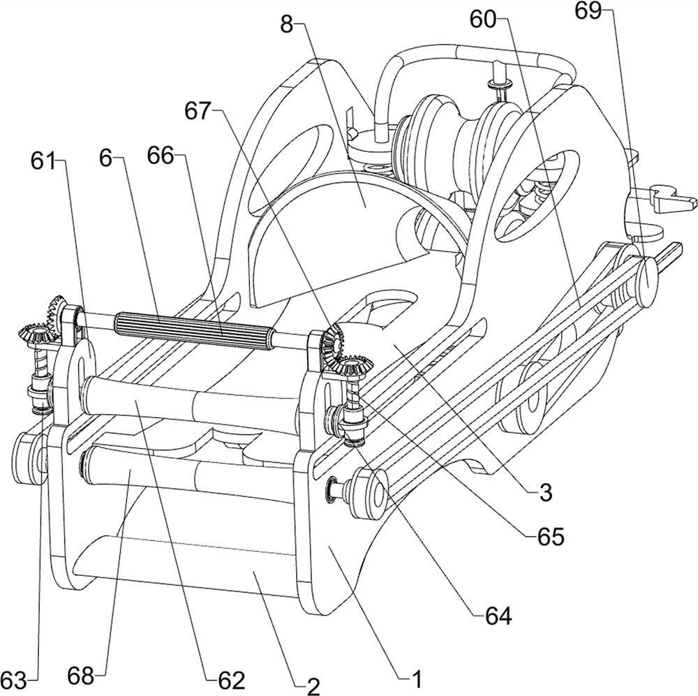
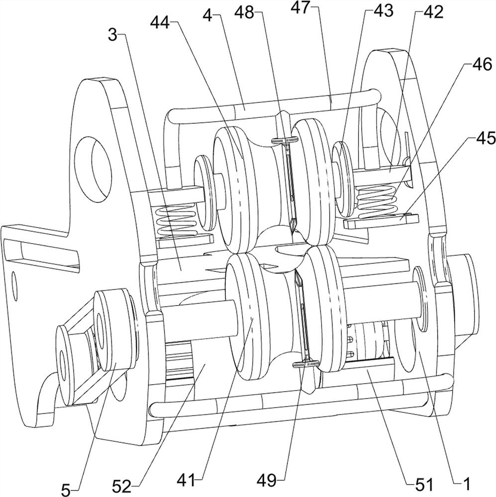
[0025] A kind of waste and old power cable sheath peeling device, such as Figure 1-2 As shown, it includes a side plate 1, a connecting plate 2 and a horizontal plate 3, a connecting plate 2 is connected between the left sides of the two side plates 1, a horizontal plate 3 is connected between the middle parts of the two side plates 1, and a cutting Component 4 and drive component 5 , the side plate 1 is provided with a cutting component 4 and a drive component 5 , and the cutting component 4 and the drive component 5 are transmission-connected.

[0026] The cutting assembly 4 includes a first roller 41, a sliding plate 42, a mounting plate 43, a second roller 44, a chassis 45, a pressure spring 46, a connecting rod 47, a first cutter 48 and a second cutter 49, two pieces A first roller 41 is rotatably connected between the lower part of the right side of the side plate 1, and a sliding plate 42 is slidably connected to the upper part of the side of the side plates 1 on both ...

Embodiment 2

[0030] On the basis of Example 1, such as image 3 As shown, transmission assembly 6 is also included, and transmission assembly 6 includes n-shaped plate 61, upper transmission roller 62, threaded sleeve 63, T-shaped sleeve plate 64, screw rod 65, rotating shaft 66, bevel gear 67, lower transmission roller 68, Transmission wheel 69 and conveyor belt 60, n-shaped plate 61 is connected to the left side of the top of both side plates 1, and an upper conveying roller 62 is slidably connected between the two n-shaped plates 61, and the upper conveying roller 62 and n-shaped plate 61 Rotate fit, the front and rear sides of the upper loser 62 are rotatably connected with a T-shaped sleeve plate 64, the T-shaped sleeve plate 64 is connected with a threaded sleeve 63, and the threaded sleeve 63 is threadedly connected with a screw rod 65, and the screw rod 65 and the n-shaped plate 61 rotating fit, rotating shaft 66 is connected between the n-shaped plates 61 tops on both sides, the t...

Embodiment 3

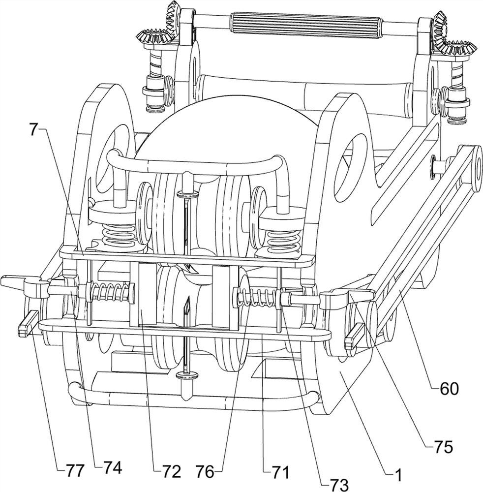
[0033] On the basis of Example 2, such as Figure 4 As shown, a cut-off assembly 7 is also included, and the cut-off assembly 7 includes a chute plate 71, a cutting piece 72, a sliding sleeve 73, a guide rod 74, an L-shaped wedge 75, a return spring 76 and a swing rod 77, and two side plates 1. A chute plate 71 is connected between the upper and lower sides on the right side, and a cutting piece 72 is slidably connected between the front and rear sides of the chute plate 71 on both sides, and the front and rear sides of the chute plate 71 on both sides are connected Sliding sleeve 73 is arranged, and cutting piece 72 is connected with guide rod 74, and guide rod 74 is slidably matched with sliding sleeve 73, is connected with back-moving spring 76 between cutting piece 72 and sliding sleeve 73, and one end of both side guide rods 74 is far away from each other. An L-shaped wedge 75 is connected, and a swing rod 77 is connected to the two conveyor belts 60, and the swing rod 77...


PUM


Abstract

The invention relates to a peeling device, in particular to a peeling device for waste and old power cables. The technical problem to be solved by the present invention is how to design a waste electric cable sheath peeling device that does not need to be operated manually and can save manpower. In order to solve the above-mentioned technical problems, the present invention provides such a device for peeling the sheath of waste electric cables, which includes: side plates, which are arranged in two pieces, and a connecting plate is connected between one side of the two side plates; It is connected between the middle parts of the two side plates; the cutting assembly is arranged on the side plates; the driving assembly is arranged on the side plates, and the cutting assembly and the driving assembly are connected by transmission. The invention achieves the effect of peeling the cable through the cooperative operation of the cutting assembly and the driving assembly.

Description

technical field [0001] The invention relates to a peeling device, in particular to a peeling device for waste and old power cables. Background technique [0002] With the continuous development of modern society and the continuous improvement of people's quality of life, in modern society, power resources are an extremely important resource. When power resources are used, cables are usually used to transmit power. Cables are usually made of It is made of one or more mutually insulated conductors and an outer insulating protective layer, which can transmit power or information from one place to another. The cable will age after being used for a long time. After the cable is aged, the cable needs to be recycled. In Cables need to be stripped for recycling. [0003] After retrieval, the authorized patent publication number is the patent of CN210246153U, which discloses a cable peeling device. The cable peeling device includes a base, a support part and a cutter, the support p...

Claims


Application Information

Patent Timeline
Patent Type & Authority Patents(China)
IPC IPC(8): H02G1/12
CPCH02G1/126
Inventor 林小换
Owner 尤海忠
Why Eureka
Try Eureka