Cable stripping device for constructional engineering

A technology for construction engineering and cables, which is applied in the field of cable stripping devices for construction engineering, and can solve the problems of unsatisfactory stripping efficiency and copper wire winding that cannot be recycled.

Pending Publication Date: 2022-04-08
苏金荣
View PDF1 Cites 0 Cited by
  • Summary
  • Abstract
  • Description
  • Claims
  • Application Information

AI Technical Summary

Problems solved by technology

[0006] In order to overcome the shortcomings of the above-mentioned patent that only one cable can be peeled at a time, the efficiency of peeling is not ideal, and the copper wire that needs to be recycled cannot be rolled up, the technical problem to be solved by the present invention is to provide a A cable stripping device for construction that can strip multiple cables at once and reel copper wires that need to be recycled

Method used


Image

  • Cable stripping device for constructional engineering
  • Cable stripping device for constructional engineering
  • Cable stripping device for constructional engineering

Examples


Embodiment 1

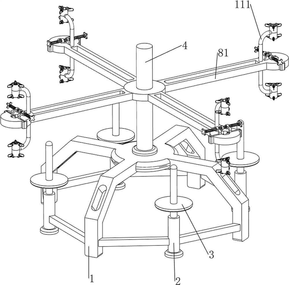
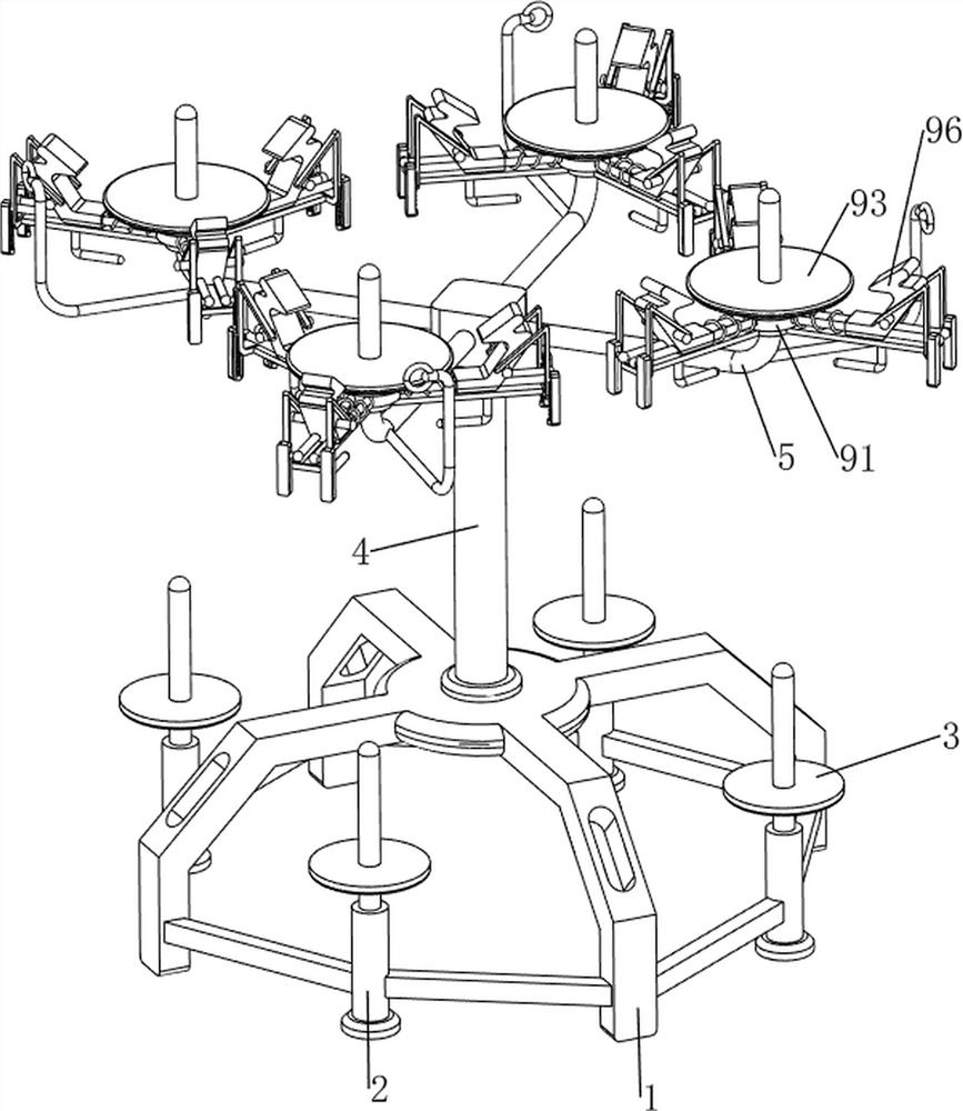
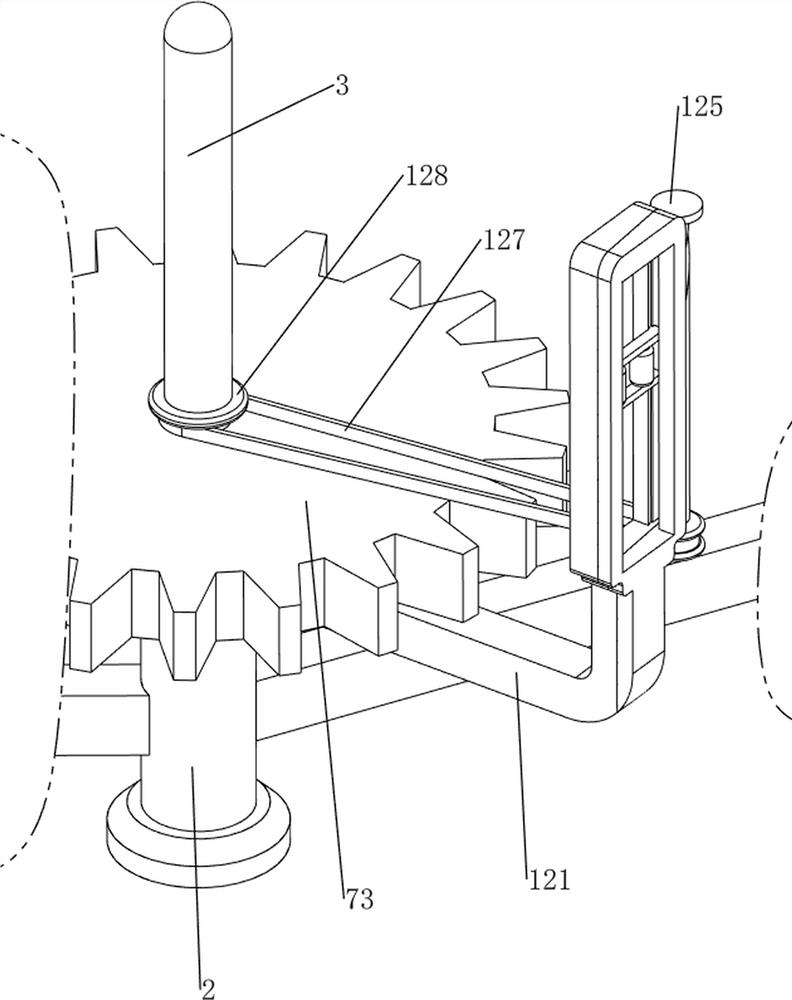
[0040] A kind of cable stripping device for construction engineering, such as Figure 1-5 As shown, it includes a support frame 1, a first installation rod 2, a turret 3, a second installation rod 4, a third installation rod 5, a guide rod 6, a power mechanism 7 and a peeling mechanism 8, and the lower part of the support frame 1 is along the circumferential direction Four first installation rods 2 are evenly spaced connected, and the upper parts of the four first installation rods 2 are connected with a turret 3 in a rotatable manner. There are four third installation rods 5 evenly spaced along the circumferential direction, and a guide rod 6 is connected to the four third installation rods 5. A power mechanism 7 is arranged between the support frame 1 and the turret 3. The second installation rod 5 Bar 4 middle part is provided with peeling mechanism 8.

[0041] Such as figure 1 , image 3 and Figure 5 As shown, the power mechanism 7 includes a frame 70, a motor 71, a f...

Embodiment 2

[0045] On the basis of Example 1, such as figure 1 , Figure 6 , Figure 7 and Figure 8 As shown, it also includes a limit mechanism 9, the third mounting rod 5 is provided with a limit mechanism 9, the limit mechanism 9 includes a mounting block 91, a first return spring 92, a pressing plate 93, a guide rod 94, a second return spring 95 , wedge-shaped block 96 and pressure bar 97, four third mounting rods 5 are connected with a mounting block 91, the mounting block 91 is located above the guide rod 6, and the outer walls of the four mounting blocks 91 are connected with three groups of guide rods 94 along the circumference , two guide rods 94 are a group, each group of guide rods 94 is slidably connected with a wedge-shaped block 96, each guide rod 94 is covered with a second return spring 95, the two of the second return spring 95 The ends are respectively connected with the mounting block 91 and the wedge-shaped block 96, and each wedge-shaped block 96 is connected with...

Embodiment 3

[0049] On the basis of Example 2, such as figure 1 , Figure 9 , Figure 10 and Figure 11 As shown, a guide mechanism 11 is also included, and the mounting plate 81 is provided with a guide mechanism 11. The guide mechanism 11 includes a fixed rod 111, a guide cylinder 112, a first connecting rod 113, a first sliding frame 114, and a second fixed block 115. , the first common spring 116 and guide wheel 117, the outside of four mounting plates 81 is all connected with a fixed rod 111, and fixed rod 111 is positioned at the inboard of first fixed block 82, and the top and bottom of four fixed rods 111 are all connected with One guide cylinder 112, the upper and lower parts of the four guide cylinders 112 on the upper side and the lower parts of the four guide cylinders 112 on the lower side are connected with three first connecting rods 113 evenly spaced, and each first connecting rod 113 top is connected with A second fixed block 115, each first connecting rod 113 tops are ...


PUM


Abstract

The invention relates to a cable stripping device for constructional engineering, which comprises a support frame, first mounting rods, rotating frames, a second mounting rod, a third mounting rod, a guide rod, a power mechanism and a stripping mechanism, and is characterized in that the lower part of the support frame is uniformly connected with the four first mounting rods at intervals in the circumferential direction, and the upper parts of the four first mounting rods are rotatably connected with the rotating frames; a second mounting rod is connected to the middle of the top of the supporting frame, four third mounting rods are uniformly connected to the upper portion of the second mounting rod at intervals in the circumferential direction, a guide rod is connected to each of the four third mounting rods, a power mechanism is arranged between the supporting frame and the rotating frame, and a peeling mechanism is arranged in the middle of the second mounting rod. According to the invention, four waste cables can be peeled at one time through the eight peeling knives, and the winding drum for winding copper wires can be driven to rotate through the rotation of the rotating frame, so that the copper wires can be wound.

Description

technical field [0001] The invention relates to a cable stripping device, in particular to a cable stripping device for construction engineering. Background technique [0002] Construction projects need to use more cables, and cables will be old and discarded after long-term use. The recycling of waste cables has important social significance. As we all know, waste materials are thrown around, which is very serious to the environment, especially cables, waste cables The valuable part of recycling is mainly the copper wire inside. When it is necessary to recycle the copper wire in the waste cable, the cable needs to be stripped first, the outer skin of the cable is peeled off, and then the copper wire inside the cable is rolled up for recycling. . [0003] After retrieval, the patent publication number is: CN209313317U patent, a cable stripping device, including a fixed ferrule, a stripping chuck and a flip sleeve, the flip sleeve is fixedly installed on one side of the fixe...

Claims


Application Information

Patent Timeline
Patent Type & Authority Applications(China)
IPC IPC(8): H02G1/12H01R43/28
Inventor 苏金荣
Owner 苏金荣
Why Eureka
Try Eureka