
offshore oil storage tank

A technology for offshore oil and storage tanks, applied in packaging, cleaning methods and appliances, chemical instruments and methods, etc., can solve the problems of low alloy steel corrosion and rust, frequent maintenance, and affecting the use of storage tanks, so as to prevent electrochemical corrosion , Avoid turning too fast, prevent rust effect

Active Publication Date: 2021-11-26
江苏微纳光膜科技有限公司
View PDF7 Cites 0 Cited by
  • Summary
  • Abstract
  • Description
  • Claims
  • Application Information

AI Technical Summary

Problems solved by technology

[0002] After oil extraction, the extracted oil will be stored in the storage tank first, and then the oil will be refined and processed. The storage tank is made of low-alloy steel material. Low-alloy steel has the characteristics of high strength and good plastic toughness. Because the oil storage tank is in On the offshore drilling platform, the sea air has high humidity and salt content, and the storage tank is exposed to the high-humidity marine atmospheric environment for a long time. The moisture and salt in the atmosphere will condense on the surface of the storage tank to form a water film, which acts as an electrolyte. , it is easy to electrochemically corrode the low-alloy steel material on the surface of the storage tank, and it is easy to corrode and rust the low-alloy steel in a high-humidity environment for a long time, requiring frequent maintenance and affecting the use of the storage tank

Method used


Image

  • offshore oil storage tank
  • offshore oil storage tank
  • offshore oil storage tank

Examples


Embodiment 1

[0025] Such as Figure 1-Figure 6 Shown:

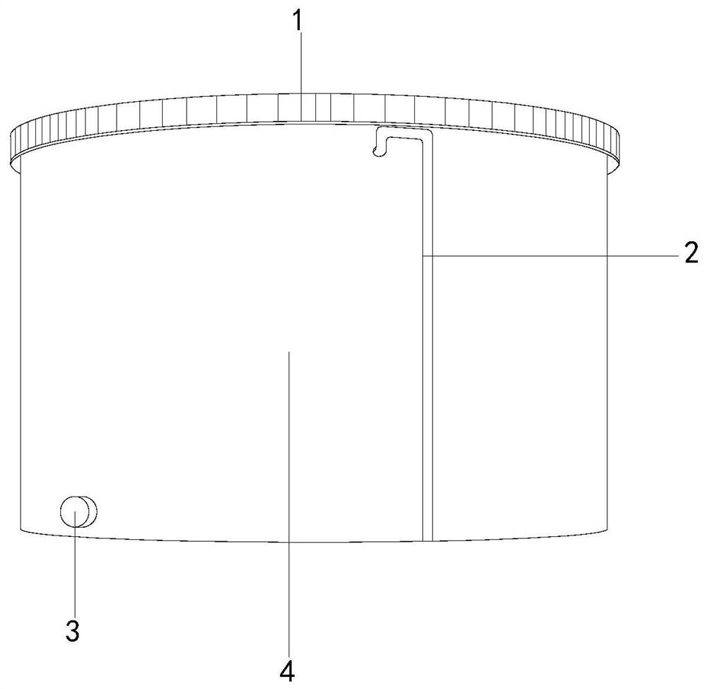
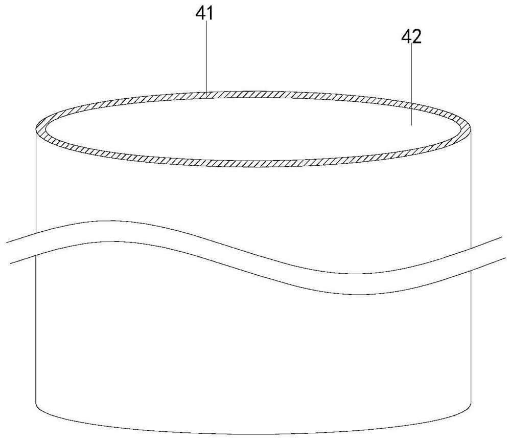
[0026] The present invention is an offshore oil storage tank, the structure of which includes a guardrail 1, an oil suction pipeline 2, an oil outlet pipe 3, and a storage tank 4. The oil suction pipeline 2 is embedded and installed on the side of the storage tank 4. The storage tank 4 is an integrated structure, the guardrail 1 is welded on the upper end of the storage tank 4, the storage tank 4 is provided with a protective mechanism 41 and a storage tank 42, and the protection mechanism 41 is attached to the outside of the storage tank 42. The upper end of the protection mechanism 41 is welded on the outside of the guardrail 1, and the protection mechanism 41 is in a ring structure, and is located on the same central axis as the storage tank 42, so that the storage tank 42 is sealed inside.

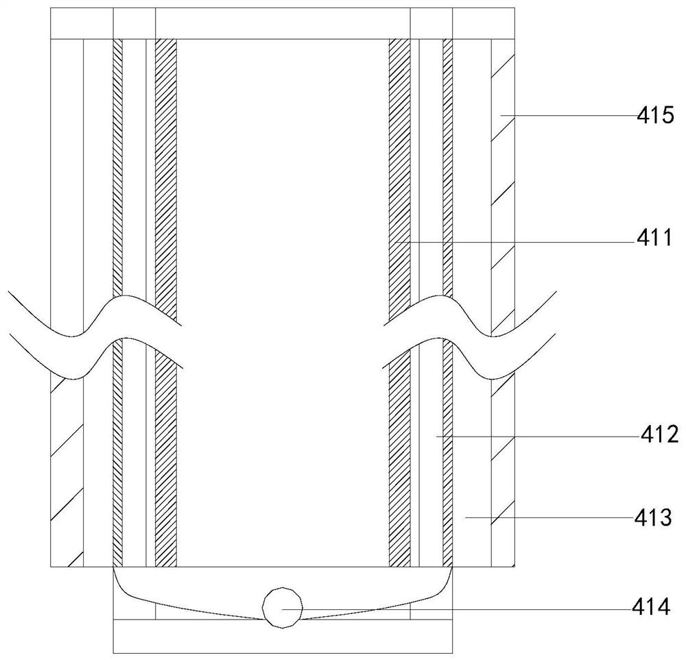
[0027] Wherein, the protective mechanism 41 is provided with a protective layer 411, a collecting tank 412, a sliding mechanism 413, a colle...

Embodiment 2

[0034] Such as Figure 7-Figure 8 Shown:

[0035] Wherein, the cleaning mechanism 415 is composed of a cleaning block c1, a threaded rod c2, a fan c3, a rotating rod c4, and a connection line c5. The connection line c5 is embedded in the upper end of the cleaning block c1, and the threaded rod c2 and the cleaning block c1 is threaded, the rotating rod c4 and the fan c3 are located on the same center line, the lower end of the connecting line c5 is embedded in the rotating rod c4, the cleaning block c1 is attached to the outside of the sliding mechanism 413, and the threaded rod c2 Shaft wheels are installed at both ends, so that the threaded rod c2 can be rotated, and the threaded rod c2 is prevented from rotating too fast.

[0036]Wherein, the cleaning block c1 is provided with a cleaning groove c11, a rotating blade c12, and a fixed block c13, the rotating blade c12 is installed on the right side of the fixing block c13, the cleaning groove c11 and the fixing block c13 are ...


PUM


Abstract

The invention discloses an offshore oil storage tank, the structure of which includes a guardrail, an oil suction pipeline, an oil outlet pipe, and a storage tank. The storage tank is provided with a protection mechanism and a storage tank. Water droplets are formed after condensation of water, and the water droplets fall during the falling process. A water film is formed after staying in the middle, and after the water drops slide from the sliding mechanism, part of it is collected on the absorbing block to prevent the water drops from stopping during the sliding process, and the groove limits the area of ​​the water drops to prevent the water drops from being too large to form Most of the water film slides down to the filter net through the inclined linear structure on the sliding bar and enters the collecting tank in the protection mechanism, avoiding the formation of water film on the surface of the storage tank and preventing electrochemical corrosion on the surface of the storage tank. Both ends of the threaded rod A shaft wheel is installed to rotate the threaded rod to avoid the threaded rod from rotating too fast. During the movement, clean the salt crystals on the surface of the sliding mechanism in the cleaning tank to prevent the salt crystals from stagnating on the surface of the storage tank and prevent the salt from causing damage to the surface of the storage tank. Rust.

Description

technical field [0001] The invention relates to the petroleum field, in particular to an offshore petroleum storage tank. Background technique [0002] After oil extraction, the extracted oil will be stored in the storage tank first, and then the oil will be refined and processed. The storage tank is made of low-alloy steel material. Low-alloy steel has the characteristics of high strength and good plastic toughness. Because the oil storage tank is in On the offshore drilling platform, the sea air has high humidity and salt content, and the storage tank is exposed to the high-humidity marine atmospheric environment for a long time. The moisture and salt in the atmosphere will condense on the surface of the storage tank to form a water film, which acts as an electrolyte. , it is easy to electrochemically corrode the low-alloy steel material on the surface of the storage tank, and it is easy to corrode and rust the low-alloy steel in a high-humidity environment for a long time...

Claims


Application Information

Patent Timeline
Patent Type & Authority Patents(China)
IPC IPC(8): B65D90/00B65D90/06B08B9/087
CPCB08B9/087B65D90/00B65D90/06
Inventor 潘勇
Owner 江苏微纳光膜科技有限公司
Learn More