

Control device for hybrid drive-type elevator
A hybrid drive and control device technology, applied in the direction of transportation and packaging, elevators, etc., can solve the problem of insufficient access to the car
- Summary
- Abstract
- Description
- Claims
- Application Information
AI Technical Summary
Problems solved by technology
Method used
Image

Examples
no. 1 Embodiment approach
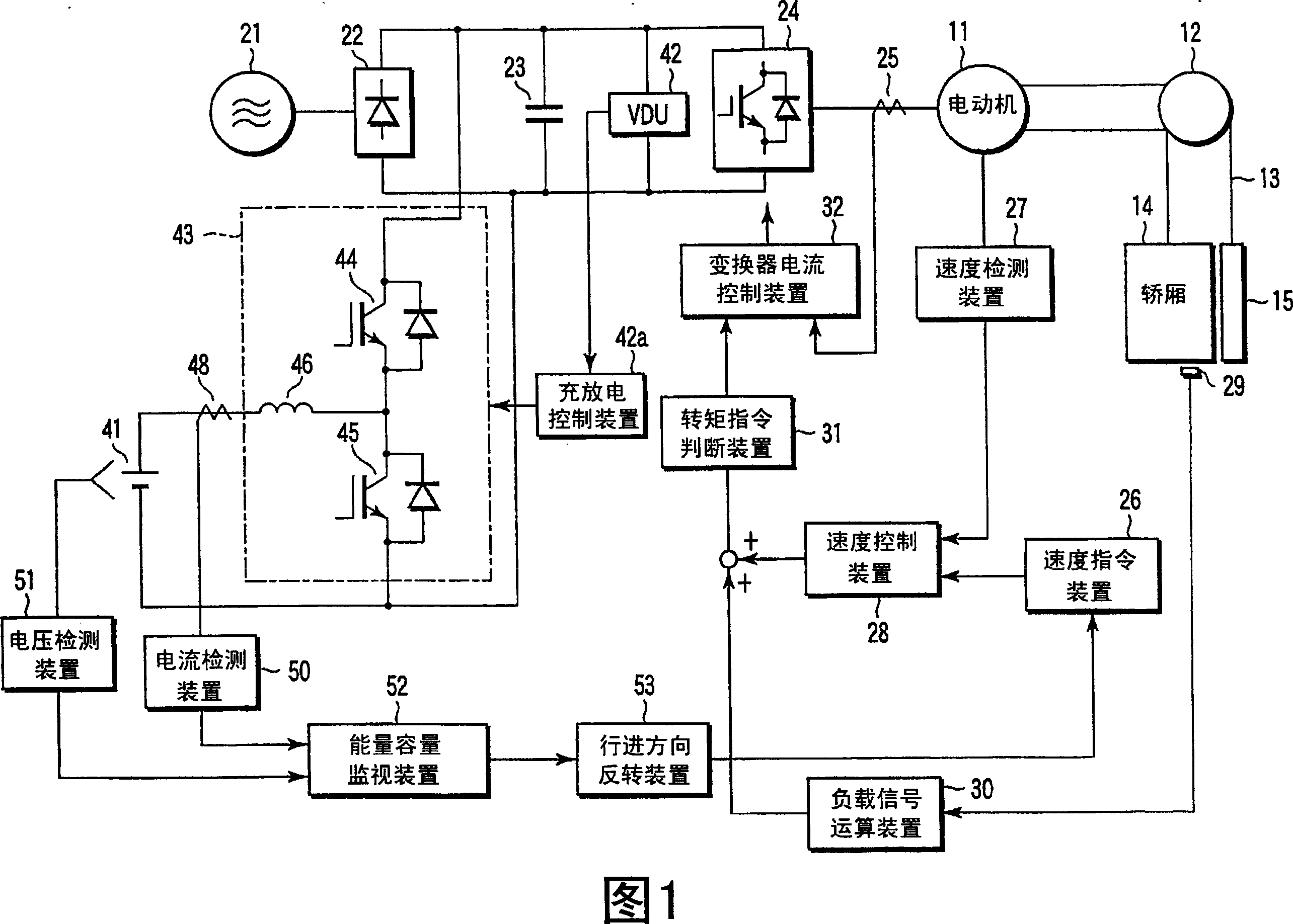
[0025] Fig. 1 is a diagram showing the configuration of a control device for a hybrid drive elevator according to a first embodiment of the present invention.
[0026] This elevator includes a motor 11 , a pulley 12 , a rope 13 , a car 14 , and a counterweight (counterweight) 15 .
[0027] The motor 11 is rotated by receiving predetermined driving power. The pulley 12 is mounted on the rotation shaft of the motor 11 . A rope 13 is wound around a pulley 12, and a car 14 and a counterweight 15 are attached to both ends thereof.
[0028] In addition, this elevator includes a commercial power supply 21 , a rectifier 22 , a smoothing capacitor 23 , an inverter 24 , and an inverter current detection device 25 as a drive system for the car 14 .
[0029] The commercial power supply 21 supplies a predetermined AC voltage to the driving system of the car 14 . The rectifier 22 converts the AC voltage from the commercial power supply 21 into a DC voltage. The smoothing capacitor 23 sm...
no. 2 Embodiment approach
[0066] Next, a second embodiment of the present invention will be described.
[0067] In the above-mentioned first embodiment, when it is detected that the capacity of the power storage device 41 is insufficient, the direction of the car 14 is reversed, but in the second embodiment, the position to determine whether to reverse direction.
[0068] Fig. 4 is a diagram showing the configuration of a control device for a hybrid drive elevator according to a second embodiment of the present invention. In addition, the same code|symbol is attached|subjected to the same part as the structure of FIG. 1 in the said 1st Embodiment, and the detailed description is abbreviate|omitted. The difference from the configuration of FIG. 1 is that a car position detector 54 is added.
[0069] In FIG. 4 , the car position detector 54 detects the position of the car 14 in the ascending and descending path, and outputs the position detection signal to the traveling direction reversing device 53 . ...
no. 3 Embodiment approach
[0079] Next, a third embodiment of the present invention will be described.
[0080] The third embodiment is characterized in that when an abnormality in the electric current of the power storage device 41 is detected during the operation of the elevator, the direction of the car 14 is reversed and stopped at the nearest floor.
[0081] Fig. 6 is a diagram showing the configuration of a control device for a hybrid drive elevator according to a third embodiment of the present invention. In addition, the same code|symbol is attached|subjected to the same part as the structure of FIG. 1 in the said 1st Embodiment, and the detailed description is abbreviate|omitted. The difference from the configuration of FIG. 1 is that a current abnormality detection device 60 is provided instead of the energy capacity monitoring device 52 .
[0082] In FIG. 6 , the abnormal current detection device 60 monitors the current value detected by the current detection device 50 for charging and disch...
PUM
 Abstract
Description
Claims
Application Information