
Ink-jet printing head splicing correction system and correction method thereof

An inkjet print head and nozzle technology, applied in the direction of printing device and printing, can solve the problems of parts processing error, calibration data does not include the movement error of the display device, and the size difference of the inkjet print head, so as to avoid the movement error. , to improve the effect of the correction effect

Active Publication Date: 2021-02-05
JIHUA LAB
View PDF12 Cites 0 Cited by
  • Summary
  • Abstract
  • Description
  • Claims
  • Application Information

AI Technical Summary

Problems solved by technology

[0003] However, due to the processing errors, installation errors and size differences of the inkjet printheads in the parts, the misalignment of multiple inkjet printheads often occurs when splicing
In order to solve the above problems, the existing correction method is to record the position coordinates of each nozzle hole by moving the microscopic observation device, and then perform ink drop calibration; but the calibration data obtained in this way does not include the movement error of the display device, and also It does not take into account the situation that some nozzles do not eject ink, resulting in no improvement in the printing effect after correction; therefore, an inkjet printhead splicing correction method and a correction system are needed to correct the misaligned inkjet printhead module. To ensure the printing effect

Method used


Image

  • Ink-jet printing head splicing correction system and correction method thereof
  • Ink-jet printing head splicing correction system and correction method thereof
  • Ink-jet printing head splicing correction system and correction method thereof

Examples


Embodiment Construction

[0036] Specific structural and functional details disclosed herein are representative only and are for purposes of describing example embodiments of the present application. This application may, however, be embodied in many alternative forms and should not be construed as limited to only the embodiments set forth herein.

[0037] In the description of this application, it should be understood that the terms "central", "lateral", "upper", "lower", "left", "right", "vertical", "horizontal", "top", The orientation or positional relationship indicated by "bottom", "inner", "outer", etc. is based on the orientation or positional relationship shown in the drawings, and is only for the convenience of describing the application and simplifying the description, rather than indicating or implying the referred device Or elements must have a certain orientation, be constructed and operate in a certain orientation, and thus should not be construed as limiting the application. In addition...


PUM


Abstract

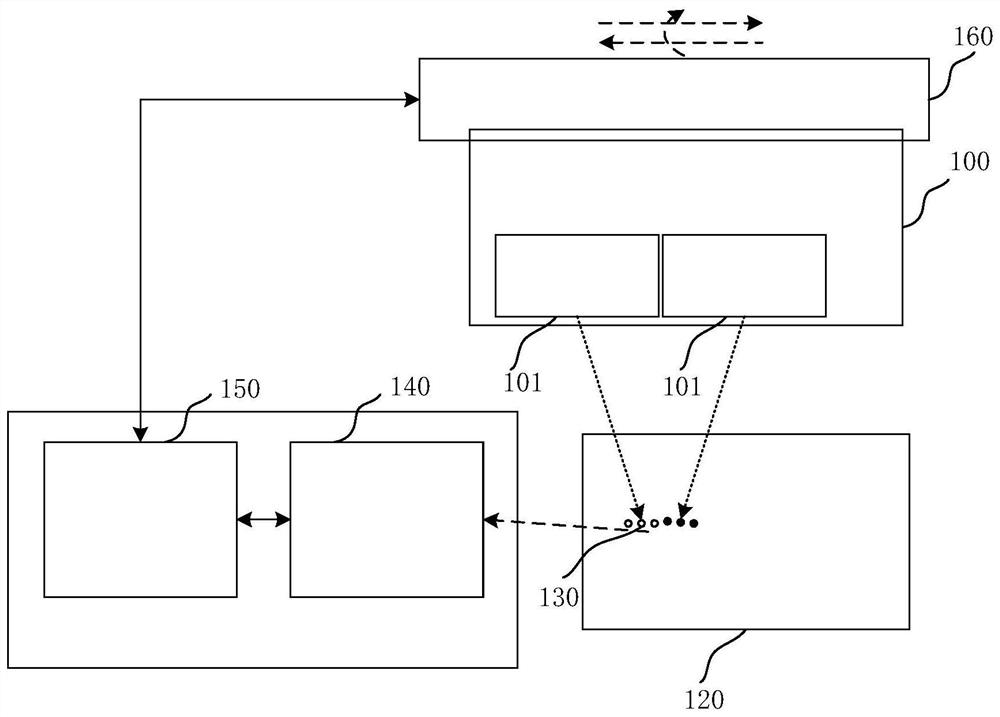
The invention discloses an ink-jet printing head splicing correction system and a correction method thereof. The ink-jet printing head splicing correction system comprises a motion control device usedfor controlling an ink-jet printing head to be detected to drip ink drops to a substrate; an observation device used for acquiring an image of the ink drops on the substrate; a processor connected tothe observation device and the motion control device; and an adjusting device connected to the motion control device and the ink-jet printing head; The processor receives the image acquired by the observation device and analyzes image information, the analyzed image information is transmitted to the motion control device, and the motion control device pushes the adjusting device to correct a splicing position of the ink-jet printing head. The problem of inaccurate alignment of the nozzle device due to offset of the ink-jet printing head during splicing caused by processing or mounting is solved; and meanwhile, the problems of motion errors caused by movement of the observation device and low correction accuracy caused by non-ink-jet of part of nozzle holes are avoided.

Description

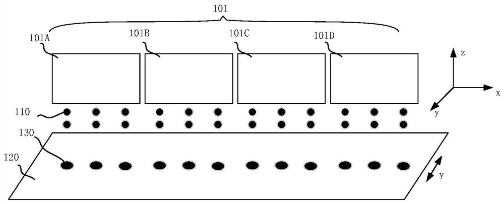
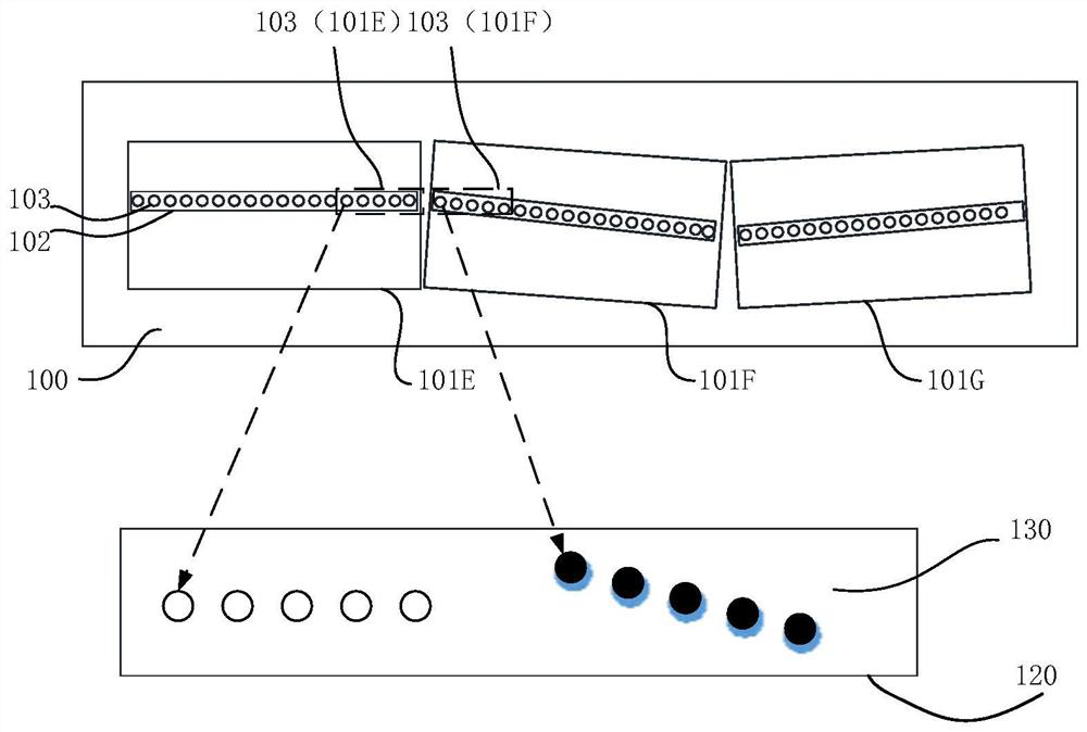
technical field [0001] The present application relates to the field of printing technology, in particular to an inkjet printing head splicing correction system and a correction method thereof. Background technique [0002] Inkjet printing has the advantages of simple and efficient processing and high material utilization, so it has been widely used in the manufacturing process of electronic devices. For example, some functional layers of OLED panels can use inkjet printing technology, usually using multiple inkjet printing Head splicing is an array of inkjet printing heads to increase the printing width, thereby improving work efficiency. In order to achieve accurate printing of spliced ​​inkjet printing electronic devices, it is usually necessary to ensure that the angles formed by the ink droplet arrays printed from the nozzle holes on the substrate are consistent. Therefore, when multiple inkjet print heads are spliced, the nozzles in the middle The starting orifice and ...

Claims


Application Information

Patent Timeline
IPC IPC(8): B41J29/393B41J2/07B41J2/11
CPCB41J29/393B41J2/07B41J2/11
Inventor 程晓鼎朱云龙张不扬
Owner JIHUA LAB
Learn More