Performance detection test bed for hydraulic mechanical continuously variable transmission
A technology of continuously variable transmission and hydraulic machinery, which is applied in the testing of mechanical components, testing of machine/structural components, measuring devices, etc., which can solve the problems of less functions, slow development, and singleness of transmission research, and reduce the number of test equipment cost effect
Pending Publication Date: 2021-02-05
NANJING AGRICULTURAL UNIVERSITY
View PDF0 Cites 6 Cited by
- Summary
- Abstract
- Description
- Claims
- Application Information
AI Technical Summary
Problems solved by technology
However, the domestic technology development of hydraulic-mechanical continuously variable transmissions is relatively slow at present. Secondly, the research on transmission test ben
Method used
View moreImage
Smart ImageViewing Examples
Examples
 PUM
 Abstract
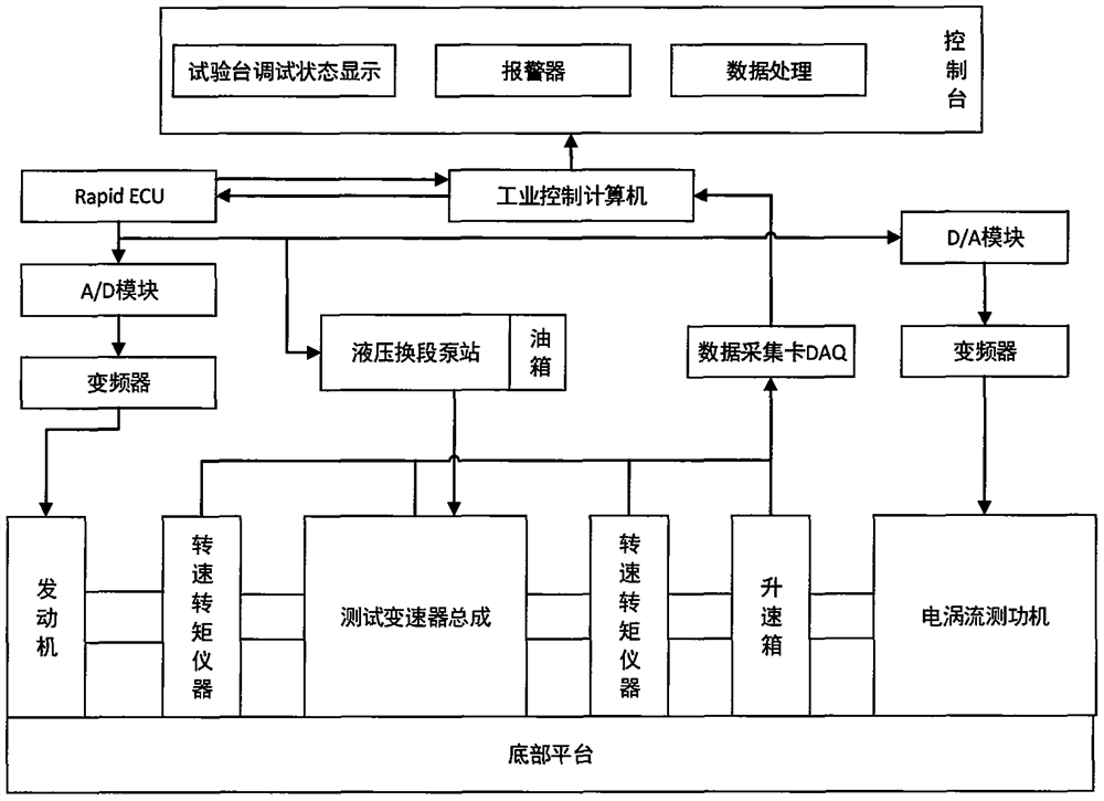
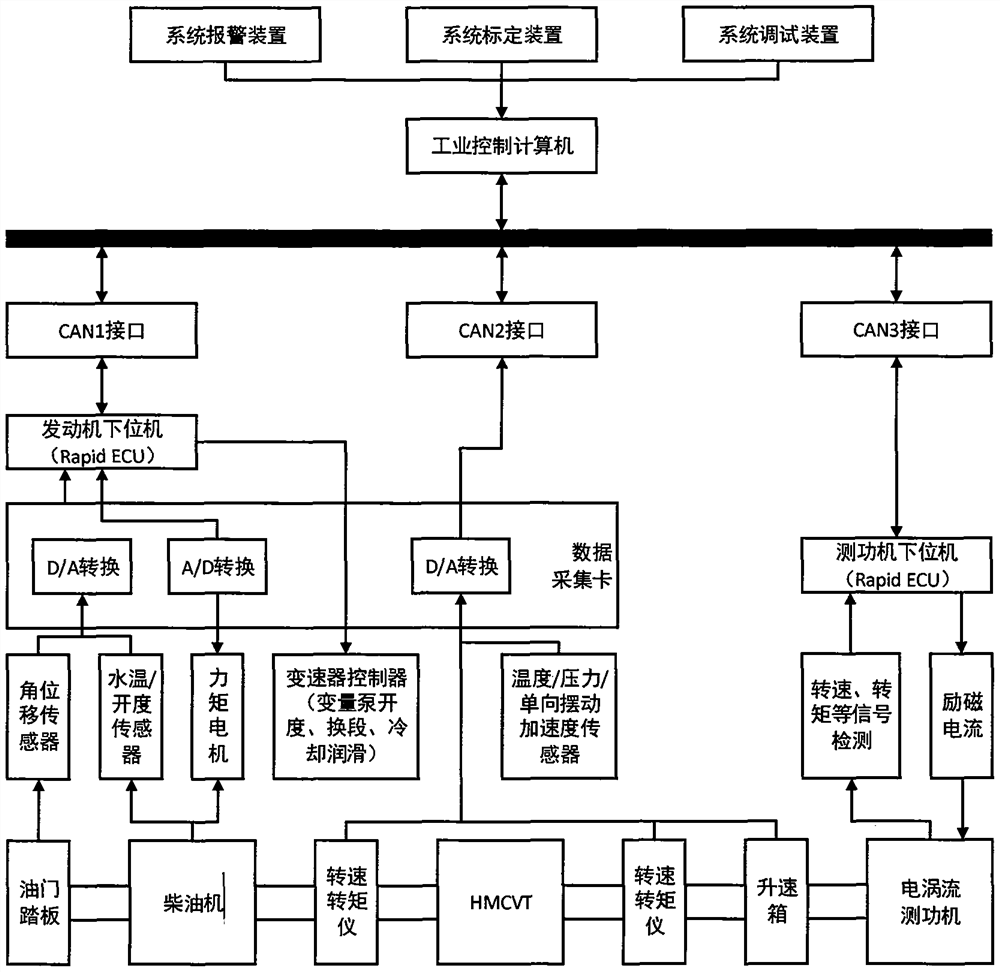
The invention discloses a performance detection test bed for a hydraulic mechanical continuously variable transmission. The performance detection test bed mainly comprises a mechanical system, a hydraulic system, a measurement and control system and a loading system. The mechanical system comprises a base platform, and a diesel engine on the base platform provides power for a transmission assemblythrough a coupler. The hydraulic system comprises a hydraulic section-changing hydraulic system, a lubricating and cooling hydraulic system and a transmission speed-regulating hydraulic system; the measurement and control system comprises an industrial personal computer, a data signal acquisition module, an actuator control module, a fault alarm module and the like; and the loading system mainlyrealizes load simulation of the gearbox to be tested under different working conditions through operation of an upper computer. Through comprehensive application of four systems of machinery, hydraulic pressure, measurement and control and loading, performance detection of the to-be-tested transmission can be realized, the performance detection mainly comprises operations of load simulation of thetested transmission, monitoring of each performance state, control of an actuator, processing and analysis of test data and the like, and certain reliability is achieved.
Description
technical field [0001] The invention belongs to the field of performance detection and control of tractor gearboxes, and in particular relates to a hydraulic mechanical stepless gearbox performance detection test bench. Background technique [0002] The hydraulic mechanical continuously variable transmission is composed of a hydraulic speed regulating mechanism and a diverting and converging mechanism. It is a new transmission form in which hydraulic power flow and mechanical power flow are connected in parallel. High transmission efficiency is achieved through mechanical transmission, and hydraulic transmission and mechanical transmission are combined. Realize stepless speed change. It has a wide range of speed changes and large transmission power, which is conducive to improving vehicle power, fuel economy and work efficiency, reducing vehicle impact and noise, realizing automatic shifting and reducing driver fatigue. It is widely used in tractors and construction machiner...
Claims
Login to View More Application Information
Patent Timeline
 IPC IPC(8): G01M13/025G01M13/022
CPCG01M13/022G01M13/025
Inventor 鲁植雄汪鹏程张文庆黄薛凯陈雷
Owner NANJING AGRICULTURAL UNIVERSITY
Features
- R&D
- Intellectual Property
- Life Sciences
- Materials
- Tech Scout
- Unparalleled Data Quality
- Higher Quality Content
- 60% Fewer Hallucinations
Learn More Browse by: Latest US Patents, China's latest patents, Technical Efficacy Thesaurus, Application Domain, Technology Topic, Popular Technical Reports.
© 2025 PatSnap. All rights reserved.Legal|Privacy policy|Modern Slavery Act Transparency Statement|Sitemap|About US| Contact US: help@patsnap.com


