Multi-component force combination calibration device loading mechanism based on electric cylinder

A technology of calibrating device and loading mechanism, which is applied in the direction of measuring device, testing of mechanical parts, testing of machine/structural parts, etc., can solve the problems of low precision of force value control, high cost and installation space, large fluctuation, etc., to reduce coupling error, ensure the rigidity of the structure, and improve the effect of control accuracy

Inactive Publication Date: 2021-02-05
BEIJING CHANGCHENG INST OF METROLOGY & MEASUREMENT AVIATION IND CORP OF CHINA
View PDF7 Cites 0 Cited by
  • Summary
  • Abstract
  • Description
  • Claims
  • Application Information

AI Technical Summary

Problems solved by technology

However, since the hydraulic cylinder is used as the power source, the device can only apply a compressive force to the sensor under test, and cannot pull the sensor under test toward calibration.
As a power source, the hydraulic cylinder has problems such as low force value control accuracy and large fluctuations when loading a small force value.
The equipment needs to use 13 loading cylinders in order to realize multi-component force combined loading calibration, and the cost and required installation space are high
At the same time, the multi-component force combined loading calibration device is affected by structural design limitations, and cannot apply a simple torque component to the sensor under test. When applying a torque component, it will inevitably introduce a force value component.
It is impossible to realize individual and combined inspection of all components of the sensor under test

Method used


Image

  • Multi-component force combination calibration device loading mechanism based on electric cylinder
  • Multi-component force combination calibration device loading mechanism based on electric cylinder

Examples


Embodiment 1

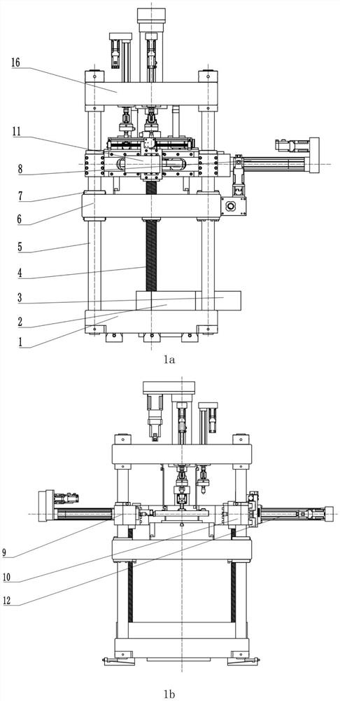
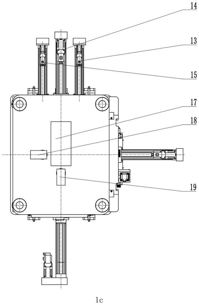
[0039] Such as figure 1 As shown in a, 1b, and 1c, the loading mechanism of a multi-component force combination calibration device based on an electric cylinder disclosed in this embodiment includes a lower base plate 1, a sprocket chain system 2, a driving motor 3, a ball screw 4, and a column 5. Mobile platform 6, hydraulic expansion sleeve 7, Y loading beam 8, X+ loading beam 9, X-loading beam 10, Y loading cylinder 11, X-loading cylinder 12, X+ pair Y-loading cylinder 13, X+ loading cylinder 14, X+ Sub Y+loading cylinder 15, upper top plate 16, Z loading cylinder 17, Z sub Y loading cylinder 18, Z sub X loading cylinder 19.

[0040] The lower bottom plate 1 is a plate-like structure. Four uprights 4 are arranged on the lower base 1 , and the uprights 4 pass through the lower base 1 and are fixed on the lower base 1 . The middle section of the column 4 passes through the X / Y direction loading beam system and is fixed with the X / Y direction loading beam system. The top of...


PUM


Abstract

The invention discloses a multi-component force combination calibration device loading mechanism based on an electric cylinder, and belongs to the technical field of large mechanical measurement instruments and equipment. The mechanism comprises a lower bottom plate, a chain wheel and chain system, a driving motor, a ball screw, a stand column, a mobile platform, a hydraulic expansion sleeve, a Yloading beam, an X+ loading beam, an X- loading beam, a Y loading cylinder, an X- loading cylinder, an X+ auxiliary Y- loading cylinder, an X+ loading cylinder, an X+ auxiliary Y+ loading cylinder, anupper top plate, a Z loading cylinder, a Z auxiliary Y loading cylinder and a Z auxiliary X loading cylinder. When a tested sensor is calibrated, the sensor is fixed on the mobile platform, and the mobile platform moves up and down to adjust the Z-direction position of the sensor. According to the invention, the defects of amulti-component force calibration device loading system can be overcome,the tested sensor is continuously loaded and calibrated, the pulling direction of the tested sensor is calibrated, all components of the tested sensor are tested independently and in a combined manner, the requirement on the number of loading cylinders is lower, and the advantages of high control precision, low cost, small installation space and the like are achieved.

Description

technical field [0001] The invention relates to a loading mechanism of a multi-component force combined calibration device based on an electric cylinder, belonging to the technical field of large-scale mechanical measuring instruments. Background technique [0002] Multi-component force sensors are widely used in various fields such as aerospace, weapon industry, processing and manufacturing. At present, the calibration methods of multi-component force sensors mainly include the following two types: 1. Process specific loading tooling according to the model of the multi-component force sensor to be tested, and carry out experiments on the traditional single-component force calibration device to realize the separation of each component of the sensor. Calibration; 2. Establish a special multi-component force combination calibration device, cooperate with special loading tooling, and realize separate calibration experiments and combined loading calibration experiments for each ...

Claims


Application Information

Patent Timeline
Patent Type & Authority Applications(China)
IPC IPC(8): G01M13/027
CPCG01M13/027
Inventor 秦海峰李鹤王露睎刘思博刘永录王磊
Owner BEIJING CHANGCHENG INST OF METROLOGY & MEASUREMENT AVIATION IND CORP OF CHINA
Why Eureka
Try Eureka