
Radar control method, radar device and mobile equipment

A radar device and radar control technology, which is applied in the field of radar detection, can solve problems such as blind areas of detection distance and increase the complexity of circuit design, and achieve the effect of simple circuit design and high flexibility

Pending Publication Date: 2021-02-05
GUANGZHOU XAIRCRAFT TECH CO LTD
View PDF0 Cites 0 Cited by
  • Summary
  • Abstract
  • Description
  • Claims
  • Application Information

AI Technical Summary

Problems solved by technology

Since the detection distance of the array antenna is set in advance, the detection distance of the existing detection scheme has the disadvantage of blind area
At the same time, it is also necessary to design multiple array antennas separately, so that each array antenna corresponds to a different detection distance, which will also increase the complexity of the circuit design

Method used


Image

  • Radar control method, radar device and mobile equipment
  • Radar control method, radar device and mobile equipment
  • Radar control method, radar device and mobile equipment

Examples


Embodiment Construction

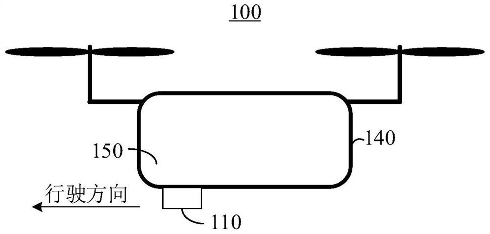
[0053] The following will clearly and completely describe the technical solutions in the embodiments of the present invention with reference to the accompanying drawings in the embodiments of the present invention. Obviously, the described embodiments are only some, not all, embodiments of the present invention. The components of the embodiments of the invention generally described and illustrated in the figures herein may be arranged and designed in a variety of different configurations.

[0054] Accordingly, the following detailed description of the embodiments of the invention provided in the accompanying drawings is not intended to limit the scope of the claimed invention, but merely represents selected embodiments of the invention. Based on the embodiments of the present invention, all other embodiments obtained by those skilled in the art without making creative efforts belong to the protection scope of the present invention.

[0055] It should be noted that relative ter...


PUM


Abstract

The embodiment of the invention provides a radar control method, a radar device and mobile equipment, and relates to the technical field of radar detection. The radar device comprises a transmitting module, a power supply module and a control module, wherein the power supply module is connected with the transmitting module through the control module, the radar device is provided with a plurality of different feed modes, and the different feed modes correspond to different feed powers; the control module is used for determining a target feed power from the plurality of feed powers, setting theelectric energy provided by the power supply module as the target feed power, and providing the target feed power to the transmitting module; and the transmitting module is used for transmitting a detection beam of which the corresponding detection distance is the target distance according to the target feed power, and the detection distances corresponding to the detection beams under different feed powers are different. The radar control method, the radar device and the mobile equipment provided by the invention have the advantages of simple design and better detection distance flexibility.

Description

technical field [0001] The invention relates to the technical field of radar detection, in particular to a radar control method, a radar device and a movable device. Background technique [0002] At present, in order to detect target objects at different distances, it is necessary to design two or more different array antennas, and each array antenna is fixed to correspond to a different detection distance. Since the detection distance of the array antenna is set in advance, the detection distance of the existing detection scheme has the disadvantage of a blind area. At the same time, it is also necessary to design multiple array antennas separately, so that each array antenna corresponds to a different detection distance, which will also increase the complexity of circuit design. Contents of the invention [0003] In view of this, the object of the present invention is to provide a radar control method, a radar device and a mobile device, which have the advantages of sim...

Claims


Application Information

Patent Timeline
Patent Type & Authority Applications(China)
IPC IPC(8): G01S13/02G01S7/02
CPCG01S13/02G01S7/02
Inventor 邓飞杨钟填荣
Owner GUANGZHOU XAIRCRAFT TECH CO LTD
Learn More