
Thermal printer

A thermal printer and heat-sensitive technology, applied in printing devices, printing, etc., can solve the problems of inconvenient adjustment of printing paper and inconvenient paper loading, and achieve the effects of convenient adjustment, convenient paper loading, and convenient use

Active Publication Date: 2021-02-09
珠海恒盛条码设备有限公司 +1
View PDF9 Cites 0 Cited by
  • Summary
  • Abstract
  • Description
  • Claims
  • Application Information

AI Technical Summary

Problems solved by technology

[0002] Now, the use of thermal printers is becoming more and more common. Many printers have external paper compartments. After replacing the paper roll, the printing paper needs to be inserted into the printer from the paper inlet. In the current printer, the hinge of the upper cover and the lower cover is located On the paper feeding route of the printing paper, the paper inlet is set at the hinged position of the upper cover and the lower cover, the paper inlet is too small, it is inconvenient to load paper, and it is also inconvenient to adjust the position of the printing paper

Method used


Image

  • Thermal printer
  • Thermal printer
  • Thermal printer

Examples


Embodiment Construction

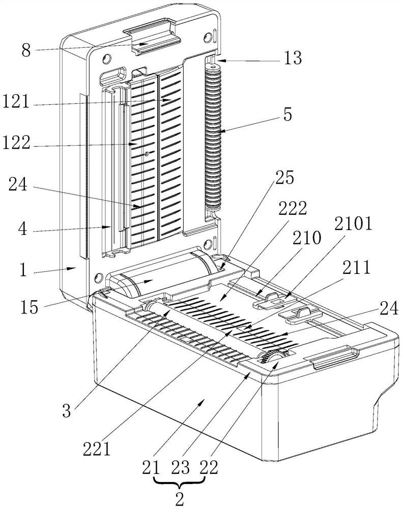
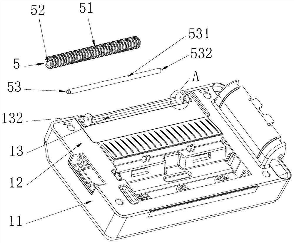
[0039] see Figure 1-Figure 3 , the invention discloses a thermal printer, comprising an upper cover 1 and a lower cover 2, the left end of the upper cover 1 and the left end of the lower cover 2 are hinged to each other, the upper end of the lower cover 2 is provided with a rubber roller 3, the The rubber roller 3 axially extends along the left and right directions, and the position corresponding to the rubber roller 3 of the upper cover 1 is provided with a thermal sheet 4, and the upper end of the lower cover 2 is also provided with a paper width adjustment mechanism 210, and the paper width adjustment The mechanism 210 includes two sliders 2101 slidingly arranged on the lower cover 2 left and right, a paper inlet and a paper outlet are provided between the upper cover 1 and the lower cover 2, and the paper inlet and the paper outlet are respectively provided on the front and back of the printer. Of course, in a thermal printer, the rubber roller 3 can also be installed on...


PUM


Abstract

The invention relates to the technical field of printers, and discloses a thermal printer. The thermal printer comprises an upper cover and a lower cover; the left end of the upper cover is hinged tothe left end of the lower cover; a rubber covered roller is arranged at the upper end of the lower cover and axially extends in the left-right direction; a thermal sheet is arranged at the position, corresponding to the rubber covered roller, of the upper cover; a paper width adjusting mechanism is further arranged at the upper end of the lower cover; the paper width adjusting mechanism comprisestwo sliding blocks arranged on the lower cover in a left-right sliding mode; and a paper inlet and a paper outlet are formed between the upper cover and the lower cover and are formed in the front endand the rear end of a printer body correspondingly. According to the thermal printer, the hinged position between the upper cover and the lower cover falls in the axial direction of the rubber covered roller and is separated from and does not interfere with a printing paper conveying path of the rubber covered roller, when the upper cover and the lower cover are opened, the paper inlet and the printing paper conveying path are opened, the paper inlet is an open space, paper loading is convenient, and the position of printing paper is convenient to adjust; and the distance between the two sliding blocks can be limited by moving the sliding blocks, and therefore the width of the printing paper is limited, and the use is convenient.

Description

technical field [0001] The invention relates to the technical field of printers, in particular to a thermal printer. Background technique [0002] Now, the use of thermal printers is becoming more and more common. Many printers have external paper compartments. After replacing the paper roll, the printing paper needs to be inserted into the printer from the paper inlet. In the current printer, the hinge of the upper cover and the lower cover is located On the paper feeding route of the printing paper, the paper inlet is set at the hinged position of the upper cover and the lower cover. The paper inlet is too small, so it is inconvenient to load paper and adjust the position of the printing paper. Contents of the invention [0003] In order to overcome the disadvantages of the above-mentioned prior art, the present invention provides a thermal printer, one aspect of which solves the problem that the paper inlet of the printer is too small. [0004] The technical scheme tha...

Claims


Application Information

Patent Timeline
Patent Type & Authority Applications(China)
IPC IPC(8): B41J2/32B41J15/04B41J29/00
CPCB41J2/32B41J15/04B41J15/048B41J29/00
Inventor 罗磊申小丹
Owner 珠海恒盛条码设备有限公司
Learn More