Construction steel bar ring high-speed hydraulic bending machine
A technology for building steel bars and bending machines, which is applied to online networks, other household appliances, household appliances, etc., can solve the problems of inconvenient gap welding, high labor intensity, and slow bending speed, and achieve high bending efficiency and high bending speed. The effect of short time and high flatness
- Summary
- Abstract
- Description
- Claims
- Application Information
AI Technical Summary
Problems solved by technology
Method used
Image
Examples
Embodiment 1
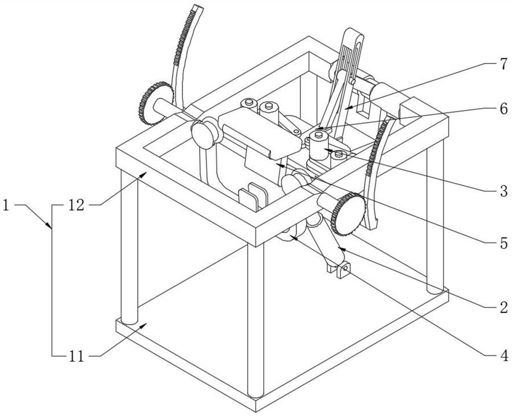
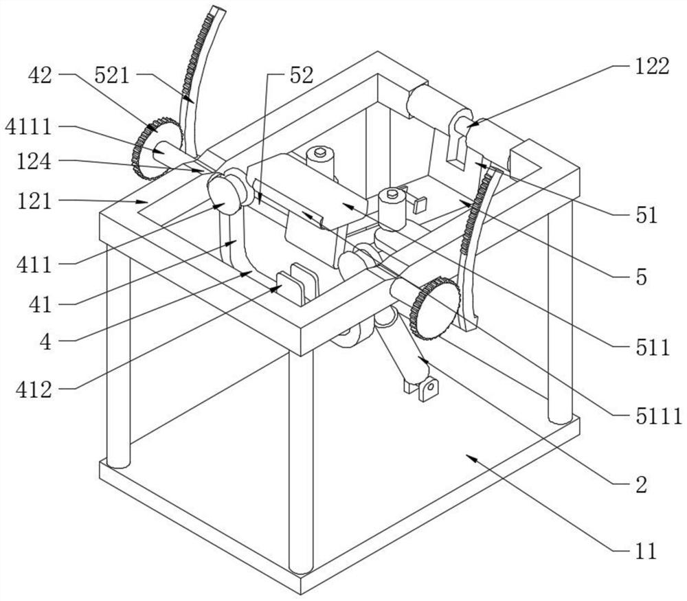
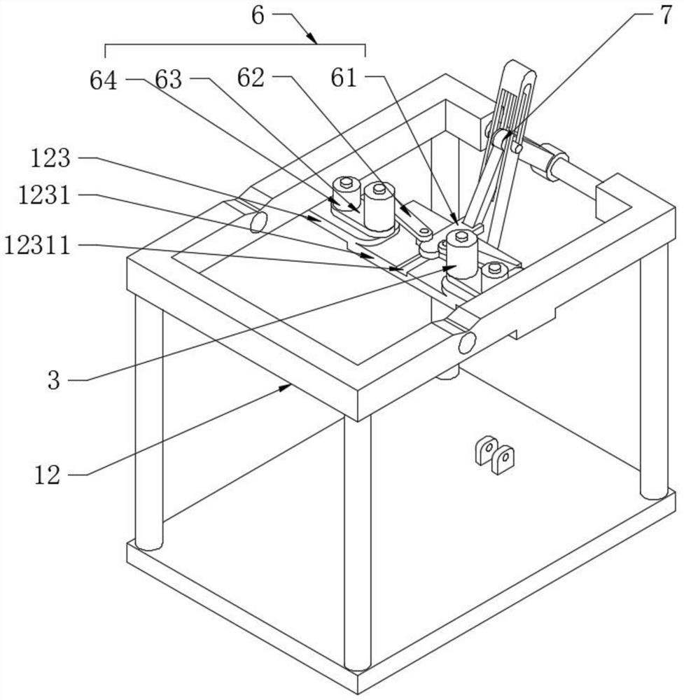
[0030] see Figure 1-3, a high-speed hydraulic bending machine for building steel rings, including a support frame 1, an oil cylinder 2 and a limit roller 3, and also includes a bending reversing frame 4, a primary bending plate 5, a secondary bending mechanism 6 and a secondary bending mechanism Bending drive combination 7, the support frame 1 is provided with a bottom plate 11 and a rectangular frame 12 on the top of the bottom plate 11, the bending commutation frame 4 includes a grooved plate 41 and a transmission gear 42, the grooved plate 41 is located in the rectangular frame 12 and its The opening end is fixedly provided with two grooved wheels 411, and the outer walls of the two grooved wheels 411 are fixedly provided with connecting shafts 4111 distributed on the same axis. Plate 121 and for rotation fit, the upper end surface of rectangular frame 12 is provided with the V-shaped groove 124 that is positioned at the top of connecting shaft 4111, is used for placing th...
Embodiment 2
[0032] see Figure 4 and Figure 5 , and the difference from Embodiment 1 is that the secondary bending driving combination 7 includes a strut 71, a strut 2 72 and a strut 3 73, one end of the strut 71 is hinged to one end of the strut 2 72, and the strut 71 The other end of the guide plate 61 is rotatably connected with the other end of the guide plate 61, the other end of the strut 72 is rotatably connected with the positioning shaft 122, and the articulated shaft between the strut 3 73 and the strut 71 and the strut 2 72 is movably connected. The movement of strut three 73 to realize the change of the angle between one end of strut one 71 and strut two 72 can control the sliding of guide plate 61, preferably one side of strut three 73 is provided with a rectangular hole for giving way 731, strut one 71 and strut two 72 run through the rectangular hole 731 giving way, and the other side of the strut three 73 runs through and is provided with the waist-shaped sliding hole 73...
PUM
 Abstract
Description
Claims
Application Information
 - R&D
- Intellectual Property
- Life Sciences
- Materials
- Tech Scout
- Unparalleled Data Quality
- Higher Quality Content
- 60% Fewer Hallucinations
Browse by: Latest US Patents, China's latest patents, Technical Efficacy Thesaurus, Application Domain, Technology Topic, Popular Technical Reports.
© 2025 PatSnap. All rights reserved.Legal|Privacy policy|Modern Slavery Act Transparency Statement|Sitemap|About US| Contact US: help@patsnap.com


