A fully automatic micro-motor iron shell capping mechanism with chipping detection function

A micro-motor, fully automatic technology, applied in the direction of manufacturing tools, metal processing equipment, metal processing, etc., can solve the problems of ensuring the stability of the sealing effect of the iron casing, and achieve the effect of stable and excellent sealing effect and quality assurance.

Active Publication Date: 2022-03-11
GAC COMPONENT CO LTD
View PDF0 Cites 0 Cited by
  • Summary
  • Abstract
  • Description
  • Claims
  • Application Information

AI Technical Summary

Problems solved by technology

[0004] The technical problem to be solved by the present invention is to provide a full-automatic micro-motor iron casing capping mechanism with a chipping detection function, so as to solve the problem that the existing capping mechanism is difficult to ensure the iron casing in the mass production of micro-motors. The problem of the stability of the capping effect

Method used


Image

  • A fully automatic micro-motor iron shell capping mechanism with chipping detection function
  • A fully automatic micro-motor iron shell capping mechanism with chipping detection function
  • A fully automatic micro-motor iron shell capping mechanism with chipping detection function

Examples


Embodiment 1

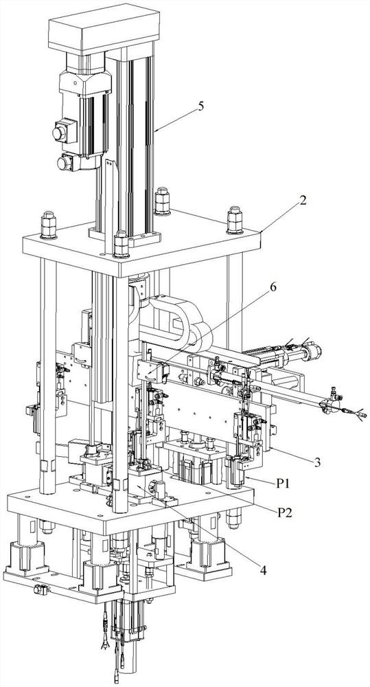
[0039] Such as Figure 1 to Figure 7 As shown, what the present invention discloses is a fully automatic micro-motor iron shell capping mechanism with a chipping detection function, which includes a frame 2 on which a feeding assembly 3, a positioning tool 4 and a servo assembly 5 are installed. The feeding assembly 3 can send the micromotor 1 to be capped from the feeding position P1 to the positioning position P2, and the positioning tool 4 can fix the micromotor 1 to be capped at the positioning position P2;

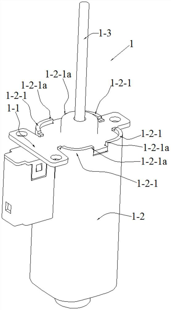
[0040] The iron casing of the micromotor 1 to be sealed is composed of an end cover 1-1 and a casing body 1-2, and the end cover 1-1 is closed at the mouth of the casing body 1-2, so The casing body 1-2 has a boss 1-2-1 protruding relative to the end cover 1-1;

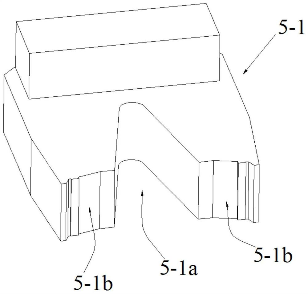
[0041] The servo assembly 5 is provided with a press knife 5-1 adopting a prolate shape, and the servo assembly 5 can drive the press knife 5-1 to turn the corners 1-2-1 of the boss 1-2-1 1a is flattened so...

Embodiment approach

[0053] see Figure 6 , the positioning tool 4 includes an in-position detection sensor 4-1, a clamping mechanism and an ejection mechanism. When the in-position detection sensor 4-1 senses that the micromotor 1 to be capped is sent to the positioning position P2, The clamping mechanism is controlled to clamp and fix the micromotor 1 to be sealed at the positioning position P2; the servo assembly 5 drives the pressing knife 5-1 to press the boss 1-2-1 The corners 1-2-1a are flattened, and when the iron casing of the micromotor 1 to be sealed is completed, the clamping mechanism is controlled to release the clamp to the micromotor 1 to be sealed. tight, and the ejection mechanism is controlled to push the uncapped micro-motor 1 that has completed the capping of the iron casing away from the positioning position P2.

[0054] The above is the basic implementation mode of the second embodiment, further optimization, improvement and limitation can be done on the basis of the basic ...

Embodiment 3

[0060] On the basis of the above-mentioned embodiment 1 or embodiment 2, this embodiment 3 also adopts the following preferred implementation modes:

[0061] see Figure 7 , the feeding assembly 3 includes a gripper mechanism 3-1 and a moving mechanism 3-2, the gripper mechanism 3-1 can grab or release the micromotor 1 to be capped, and the moving mechanism 3- 2. The jaw mechanism 3-1 can be driven to move between the feeding position P1 and the positioning position P2. Wherein, the jaw mechanism 3-1 can adopt a jaw cylinder 3-1-1 with two piston rods that can expand and contract back, and the two piston rods of the jaw cylinder 3-1-1 respectively It is realized by fixing the jaw 3-1-2; the moving mechanism 3-2 can be realized by combining several translation mechanisms in different directions according to the relative positions of the feeding position P1 and the positioning position P2.

[0062] The above is the basic implementation of the third embodiment, further optimiza...


PUM


Abstract

The invention discloses a full-automatic micro-motor iron shell capping mechanism with the function of detecting knife collapse, which is provided with a press knife adopting a flat and long shape. After fixing, the servo assembly drives the pressing knife to flatten the corners of the boss of the micro-motor to be sealed, so that the flattened corners press and fix the end cover on the casing body, realizing the Automatic capping of the iron casing of the capping micro-motor; and, by setting up a vision system, it can deal with the defect that the flat and long press knife is prone to chipping when capping a large number of micro-motors to be capped , use the vision system to detect whether there is a broken knife in real time, so that the broken knife can be found and replaced in time, and the sealing effect cannot be guaranteed due to the flattening of the corners by the pressed knife with the broken knife .

Description

technical field [0001] The invention relates to a micro-motor shell sealing device, in particular to a full-automatic micro-motor iron shell capping mechanism with a chipping detection function. Background technique [0002] In the production process of the micro-motor, when the rotor and other components of the micro-motor are assembled into the casing body, and the end cover is closed on the mouth of the casing body to become a micro-motor to be sealed, the end cover needs to be It is press-fitted with the casing body for sealing, so as to be integrated into the casing of the micro-motor. And as figure 1 As shown, for the micromotor 1 to be sealed with an iron casing, the end cover 1-1 and the casing body 1-2 need to adopt the following sealing method: the end cover 1-1 is closed on the casing body At the mouth of 1-2, there is a boss 1-2-1 protruding from the end cover 1-1 on the casing body 1-2, and the edge of the boss 1-2-1 is pressed by driving the pressing knife. ...

Claims


Application Information

Patent Timeline
Patent Type & Authority Patents(China)
IPC IPC(8): B23P19/00B23P19/027
CPCB23P19/027B23P19/00
Inventor 陈宏炜陈建国周涛吴建军
Owner GAC COMPONENT CO LTD
Why Eureka
Try Eureka